3
TREND
TILT
RIGHT
BACK
DOWN
TABLE
DOWN
LEG
DOWN
REFLEX
BRAKE
UNLOCK
REV.
TREND
TILT
LEFT
BACK
UP
TABLE
UP
LEG
UP
FLEX
POWER ON
RETURN
*
PRESS TO LOCK BRAKES
*
CLIP
FUNCTION
BUTTONS
POWER
INDICATOR
1-4. Floor Lock/Brake System
The floor lock/brake system consists of four self-
leveling, hydraulic brake cylinders which raise and
support the table base off from the casters. Press
the TABLE UP button on the pendant control to set
the table’s brakes. An electronic timer will activate
the brake system until the brakes are completely
set, approximately 8-10 seconds.
NOTE
Activating any function button will acti-
vate the brake system. Using the
TABLE UP function to set the brakes
provides a visual assurance that the
brakes are locked. As the brake cylin-
ders are extending, the entire table will
move slightly. When the table top be-
gins to elevate, the brakes are fully
locked.
To unlock the brakes, press the BRAKE UNLOCK
button and release. The brakes will retract auto-
matically in approximately 7-8 seconds.
WARNING
DO NOT unlock brakes when a patient
is on the table. An uneven patient
weight load may cause instability.
NOTE
In case of a power failure or an electri-
cal problem within the table, the emer-
gency brake release system can be
used to move the table. The control
lever for this function is located on the
side of the table base and is identified
by an EMERGENCY BRAKE RELEASE
label. Turn the lever counterclockwise
to release the brakes.
IMPORTANT
•The Emergency Brake Release Valve
must be closed and tightened (clock-
wise) before any hydraulic function will
operate.
•If the Emergency Brake Release Valve
has been operated, the BRAKE UN-
LOCK button on the pendant control
will have to be pressed before brakes
will lock again.
1-3. Pendant Control Unit
The hand-held pendant control unit (figure 1-3) has
a non-slip rubber cover which assures a positive
grip during use. A spring clip hanger located on the
back of the control allows it to be stored on the
trendelenburg cylinder cap bracket or the table
side rails.
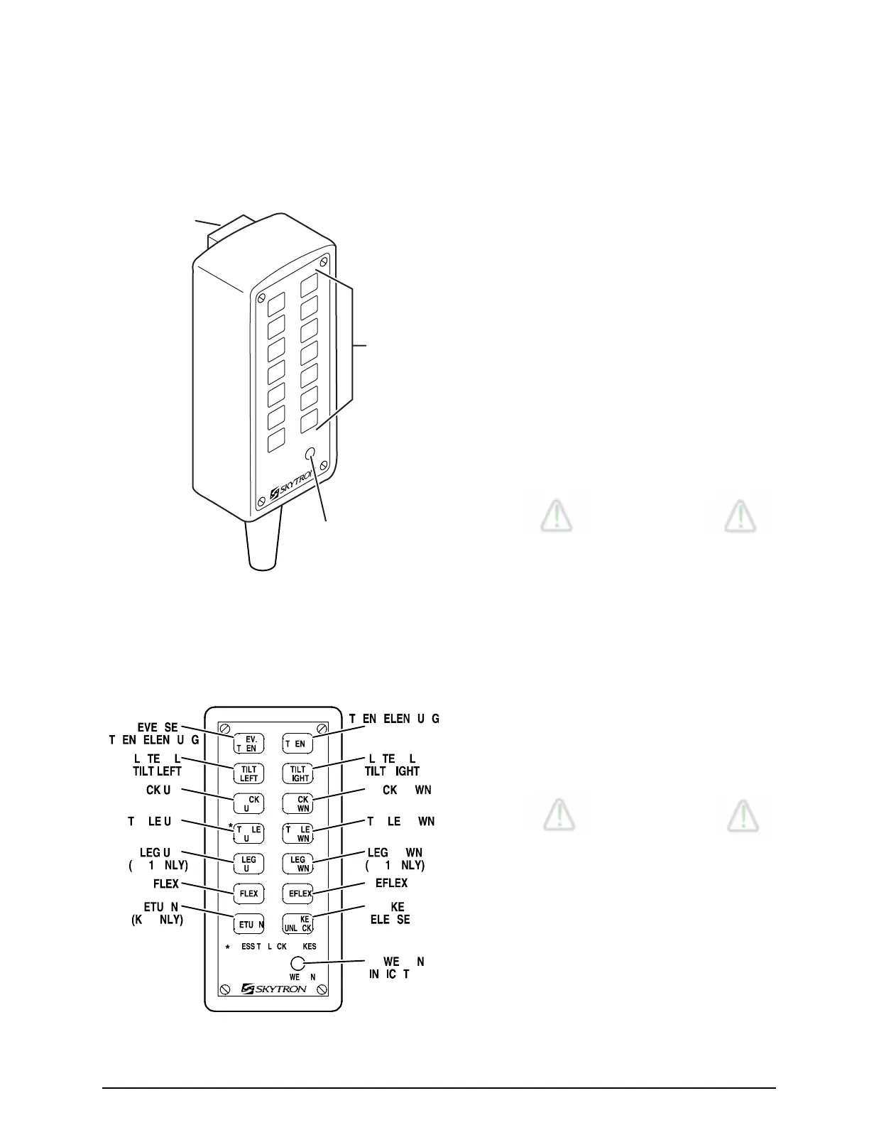
Figure 1-3. Pendant Control Unit
The function push buttons are identified with ab-
breviated descriptions for all functions. See figure
1-4. The trendelenburg and table up buttons are
red, the remaining buttons are all black.
Figure 1-4. Function Push Buttons

 Loading...


