5
FUNCTION CONTROL
ACCESS DOOR
NOTE
Battery Operation must be turned OFF
at the pendant control. It can not be
turned Off using the main power switch.
2-3. Automatic Shut-Off
a. To prevent unnecessary discharge of the
battery, a timer is built into the battery circuit. This
timer will automatically shut the battery power OFF
after 3-4 hours of table inactivity.
b. To turn the table “ON” again, simply press the
BATT button on the pendant control and the amber
indicator light will illuminate. Select any control
button to operate the table.
2-4. Charging the Battery
a. If the battery needs to be charged when
operating the table on battery power, the amber
indicator light on the pendant control will begin to
blink. At this time the battery needs to be re-
charged.
NOTE
When the amber light starts to blink
(indicating low power in battery) the
table will operate for approximately 5
continuous minutes, typically long
enough to use the table for the rest of
the day.
b. To recharge the battery simply plug the
power cord into a 120VAC wall outlet, if not
already plugged in. Turn the main power ON/
OFF switch ON by depressing it. The green battery
charging light, located next to the power cord, will
illuminate.
c. A full battery charge will last approximately 2
weeks under normal operating conditions. How-
ever, it is recommended to charge the batteries at
the end of each week to establish a normal routine
protocol.
NOTE
The table can be operated on 120VAC
power while the battery is being re-
charged. The green AC 120V indicator
light (on the pendant control) will illumi-
nate confirming 120VAC operation.
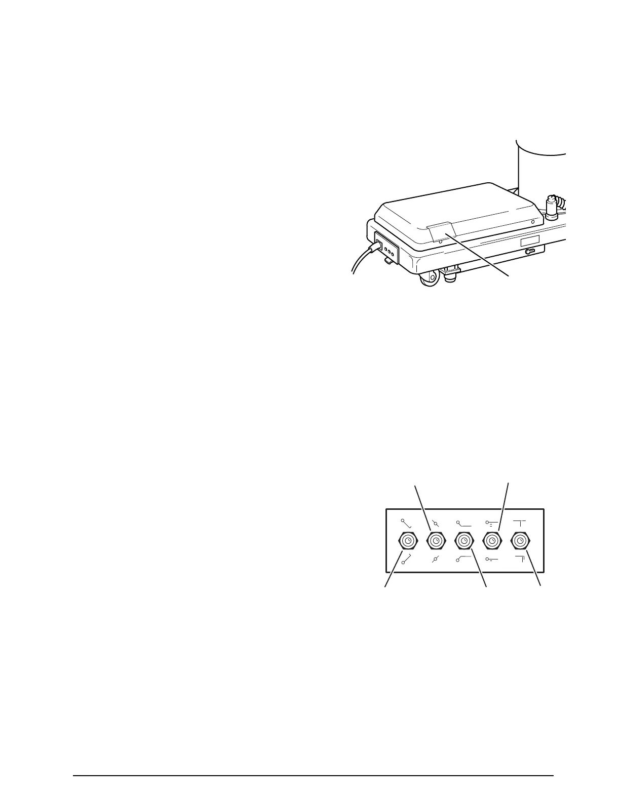
Figure 2-3. Emergency Controls Location
b. In the event of either a power failure or a
problem with the hand-held pendant control, the
table can be operated using the emergency back-
up switches. Simply push the desired emergency
switch in the appropriate direction to operate the
table functions. See figure 2-4. These switches are
spring-loaded so they return to the neutral or
center position when released.
2-5. Emergency Back-up Controls
a. The emergency back-up control switches are
located under the access door on the service
access cover in the table base. See figure 2-3.
Figure 2-4. Emergency Back-Up Controls
NOTE
The emergency back-up control
switches will function when the table is
operating on 120VAC power, battery
power, or turned off.
LAT. TILT
LEFT/RIGHT
TREND
REV. TREND
BACK
UP/DOWN
LEG
UP/DOWN
TABLE
UP/DOWN

 Loading...


