Page 13
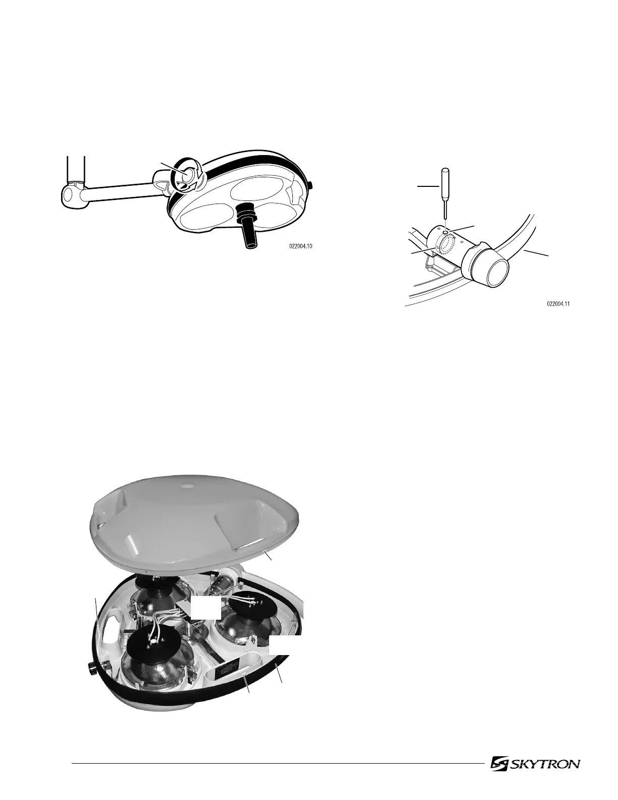
Figure 4-3. Top Cover Removal
4-2. Lighthead Pitch Adjustment
a. Check the pitch axis tension of each lighthead
by moving it through its full range of motion. See
figure 4-2.
Figure 4-2. Lighthead pitch
b. The lighthead should move freely yet main-
tain its position without drifting. If an adjustment is
required, remove the top cover and proceed as
follows:
1. Carefully move trim strip for access to
the corner plate screws and remove the (3) top
screws. See figure 4-3.
2. Using a 1/8" straight blade screwdriver,
release the (4) lock tabs and remove the top cover.
c. Rotate the lighthead until an allen set screw
is visible through the adjustment hole. Loosen the
set screw, rotate the lighthead 180 ° and loosen the
second set screw. See figure 4-4.
PITCH
PIN PUNCH
HOLE
YOKE
SET
SCREW (2)
LOCK
TAB
LOCK
TAB
TRIM
STRIP
CORNER
PLATE
LOCK
TABS
ACCESS
HOLE
Figure 4-4. Lighthead pitch adjustment
d. Rotate the lighthead until a hole is visible and
insert a pin punch into the hole in the adjustment
nut.
e. With the nut held captive with the pin punch,
rotate the lighthead clockwise to increase the fric-
tion or counterclockwise to decrease the friction.
f. Remove pin punch and check adjustment.
Tighten set screws when adjustment is complete.
g. Install top cover and secure with the (3)
screws removed from the corner plates. Do not
overtighten screws.

 Loading...


