Page 17
Figure 4-13. Top Cover Removal
360˚
E
Figure 4-12.
c. If releveling the mounting plate does not
correct the drift, or the Radial Arms are difficult to
move, the bearing preload must be adjusted. This
requires the use of special tools. Contact your
SKYTRON dealer for assistance.
4-7. Bulb Voltage Adjustment
To insure maximum intensity and to prolong bulb
life, the voltage applied to the lighthead should be
20VAC ± 0.2V. Use the following procedures to
test and adjust the bulb applied voltage.
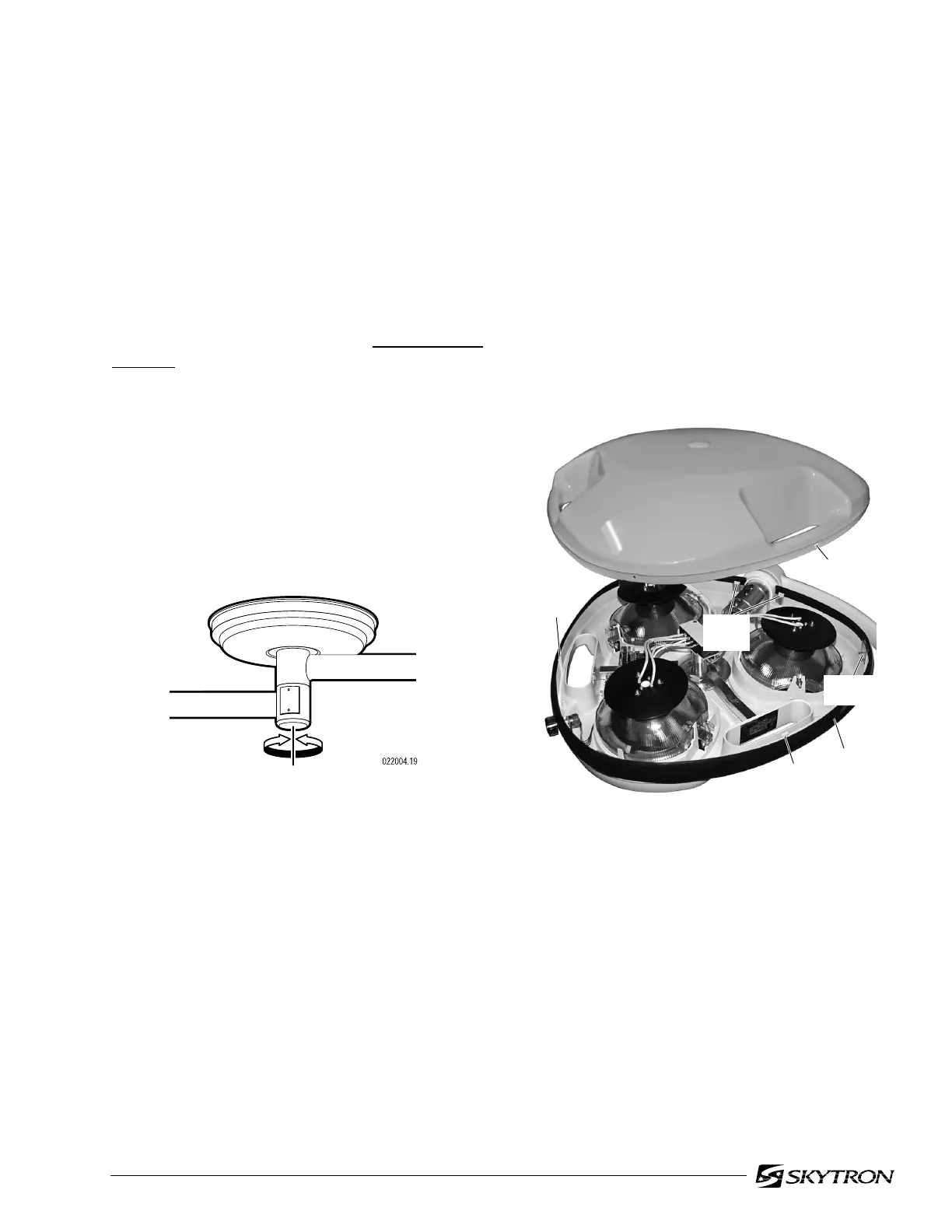
Remove the top cover using the following proce-
dure: See figure 4-13.
a. Carefully move trim strip for access to the
corner plate screws and remove the (3) top screws.
b. Using a 1/8" straight blade screwdriver,
release the (4) lock tabs and remove the top cover.
4-6. Radial Arm Horizontal Rotation
Adjustment
a. Check the horizontal rotation axis tension by
moving the Radial Arms through their full range of
travel around the center mounting hub. Refer to
figure 4-12.
b. The Radial Arms should maintain their
position without drifting yet move freely around the
hub. Normally this adjustment is correct from the
factory and does not change. If the Radial Arms
drift, the most probable cause is an
unlevel mount-
ing plate.
NOTE
Recheck the mounting plate to make
sure it is absolutely level. In most
cases releveling the plate will solve any
drifting problem.
LOCK
TAB
LOCK
TAB
TRIM
STRIP
CORNER
PLATE
LOCK
TABS
ACCESS
HOLE

 Loading...


