Page 18
ST19 Models
a. Test bulb voltage at the terminal strip. Turn
main power "ON" and set the Dimmer Control to
maximum intensity for the test. Output voltage (at
the terminals) should be 20V± 0.2V. See figure 4-
14.
LIGHT TERMINALS
TERMINAL STRIP
Figure 4-14. Bulb Voltage Test
NOTE
The internal circuitry used in the Stellar
system requires the use of a true RMS
type digital voltmeter to accurately
set the bulb voltage. Premature bulb
failure will result from incorrect voltage.
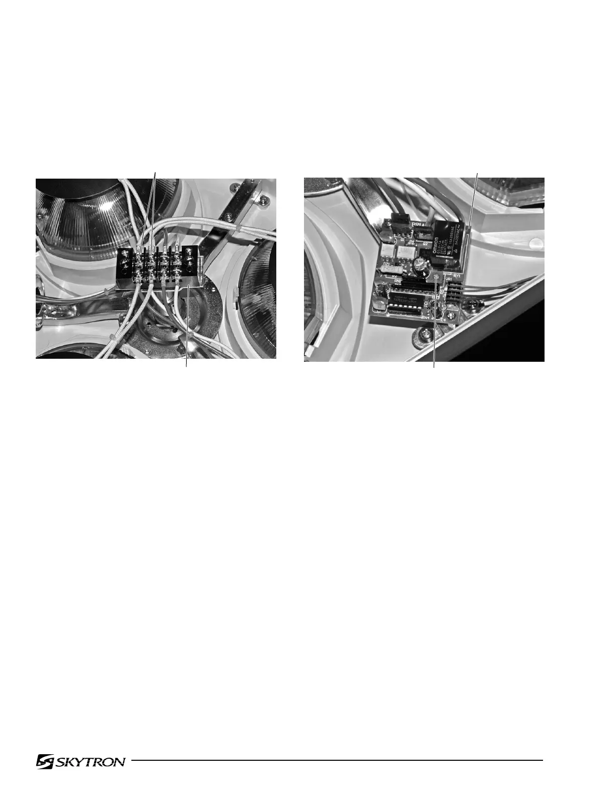
b. Adjust the voltage to the lighthead by turning
the adjuster on the lighthead circuit board. See
figure 4-15.
CIRCUIT BOARD
ADJUSTER
Figure 4-15. Voltage Adjustment (ST19)
c. Turn the adjuster clockwise to increase the
output voltage, counterclockwise to decrease the
voltage.
d. Install top cover and secure with the (3)
screws removed from the corner plates. Do not
overtighten screws.

 Loading...


