Page 7
SECTION II OPERATION
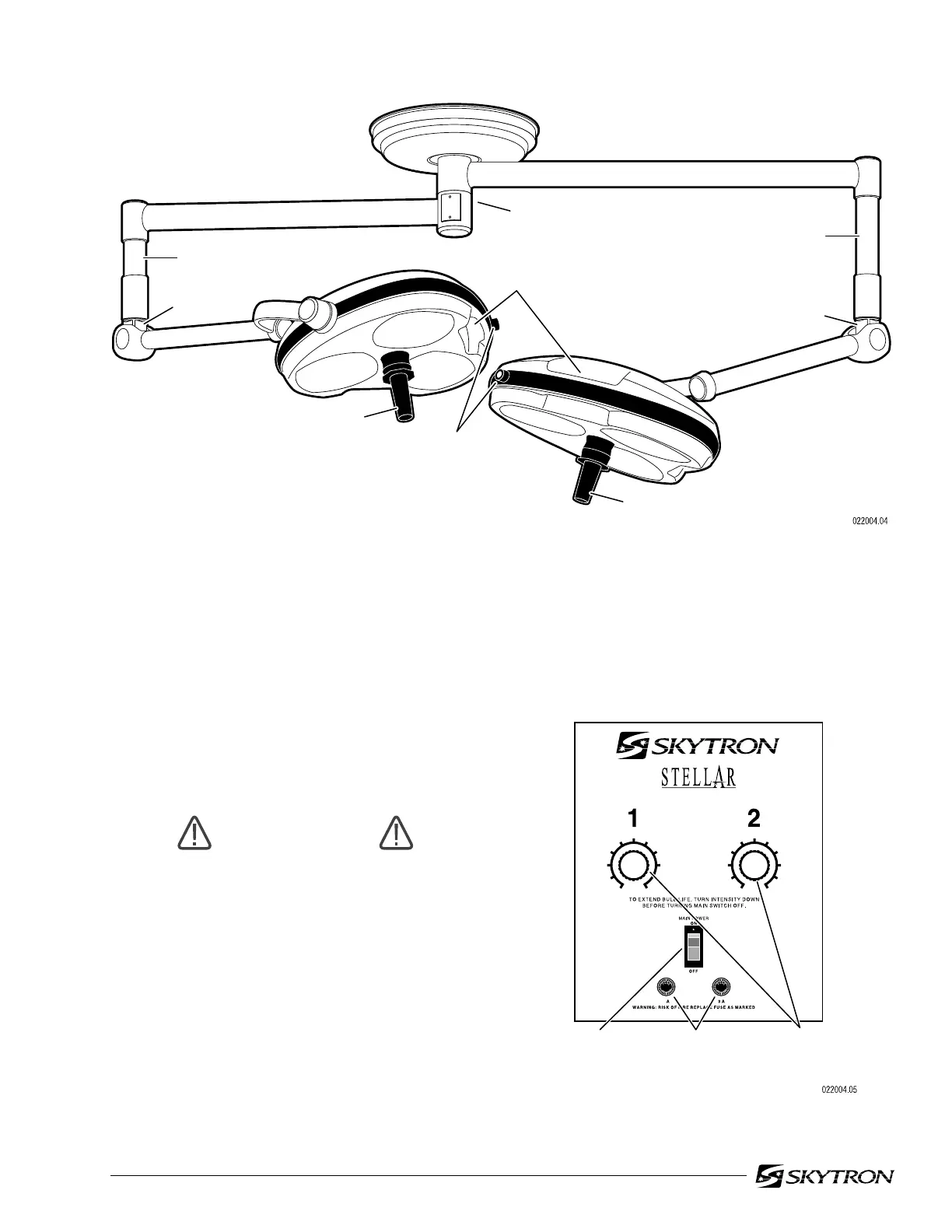
Use the following instructions to operate the light
fixture:
a. Position the lightheads as required by grasp-
ing the lighthead positioning handles and moving
the lighthead to the desired position. See figure 2-
1.
WARNING
DO NOT use this fixture in the presence
of FLAMMABLE GASES.
b. Turn the light fixture main power switch "ON"
at the wall mounted switch or Wall control (ST19WC
& ST1919WC models) and select the desired in-
tensity for each lighthead as required. See figure 2-
1 or 2-2. The mid-range position will provide ad-
equate illumination for most procedures. Full inten-
sity will usually only be required for extreme deep
cavity cases.
Figure 2-1. Dual Lighthead Fixture
NOTE
To prolong bulb life, the sof-start bulb
protection circuit will cause a slight delay
before the bulbs will illuminate.
VERTICAL SUPPORT TUBE
VERTICAL SUPPORT TUBE
BALANCE MECHANISM
BALANCE
MECHANISM
RADIAL ARM ASSEMBLY
STERILIZABLE
POSITIONING HANDLE
STERILIZABLE
POSITIONING HANDLE
POSITIONING
HANDLES
INTENSITY
CONTROL KNOBS
SAFETY
FUSES
MAIN
POWER
SWITCH
6
010
19
28
37
4
5
6
010
19
28
37
4
5
INTENSITY
CONTROL
KNOBS
3
Figure 2-2. ST1919WC Wall Mounted
Control Box

 Loading...


