Page 15
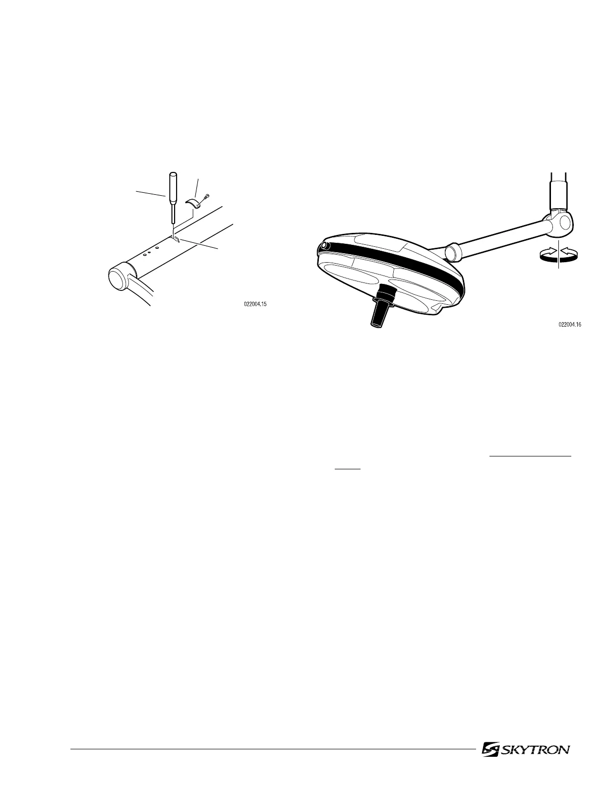
4-5. Lighthead Horizontal Rotation
Adjustment
a. Check horizontal rotation axis adjustment by
moving the lighthead through its full range of travel
around the Balance Mechanism. See figure 4-9.
HORIZONTA
ROTATION
ADJUSTMENT
SLOT
COVER
PLATE
PIN
PUNCH
Figure 4-9. Horizontal Rotation
b. The lighthead should maintain its position
without drifting, yet move freely around the Balance
Mechanism. Normally this adjustment is correct
from the factory and does not change. If the lighthead
drifts, the most likely cause is an unlevel mounting
plate.
b. The lighthead should move freely yet main-
tain its selected position within the range of motion
without drifting. If an adjustment is necessary,
refer to figure 4-8, and proceed as follows:
Figure 4-8. Vertical Travel Adjustment
c. Remove two screws securing the cover
plate and remove the cover plate from the Horizon-
tal Support Arm.
d. Pull the lighthead downward until the adjust-
ment nut is visible through the adjustment slot in the
support arm.
e. Insert a pin punch through the adjustment
slot and into a hole of the spring tension adjustment
nut. Using the pin punch, turn the adjustment nut
clockwise to increase the tension, counterclock-
wise to decrease the tension.
f. Remove the pin punch, check and repeat
adjustment procedure as necessary to achieve
proper spring tension. The lighthead should be able
to hold its position at any angle from the VST.
g. Reinstall cover plate on the Horizontal
Support Arm.

 Loading...


