Page 14
Figure 4-7. Lighthead Vertical Travel
VERTICAL
TRAVEL
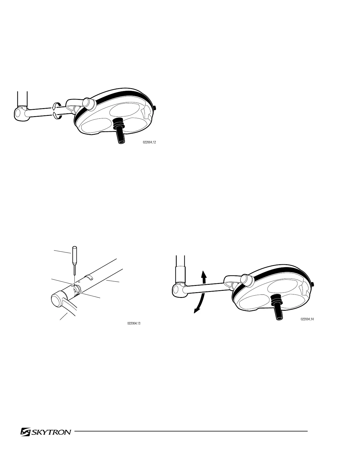
4-3. Lighthead Roll Adjustment
a. Check the roll axis tension of the lighthead by
moving it through its full 360° range of travel. See
figure 4-5.
Figure 4-5. Lighthead Roll
b. The lighthead should move freely yet main-
tain its position without drifting. If an adjustment is
required, refer to figure 4-6 and proceed as follows:
Figure 4-6. Roll Adjustment
c. Rotate the yoke until an allen set screw is
visible through the adjustment hole and loosen the
set screw. Rotate the yoke 180° and loosen the
second set screw.
d. Continue to rotate the yoke until a 5mm hole
is visible through the hole. Insert a pin punch into
the hole in the adjustment nut.
e. With the tension nut held captive with the pin
punch, rotate the yoke clockwise (viewed from the
front) to increase the friction and counterclockwise
to decrease the friction.
f. Remove pin punch and check the lighthead
for proper tension. Repeat adjustment procedure if
necessary. After the adjustment is correct, be sure
to tighten the set screws.
4-4. Vertical Travel Tension Adjustment
a. Check the adjustment of the Balance Mecha-
nism for its capacity to support the lighthead through-
out its range of vertical motion. See figure 4-7.
SUPPORT
ARM
YOKE
SET SCREW (2)
HOLE
PIN
PUNCH
ROLL

 Loading...


