Si5338-RM
8 Skyworks Solutions, Inc. • Phone [781] 376-3000 • Fax [781] 376-3100 • sales@skyworksinc.com • www.skyworksinc.com
Rev. 1.4 • Skyworks Proprietary Information • Products and Product Information are Subject to Change Without Notice • 2021
3.2. Calculating MultiSynth Values
Because of its flexibility, the Si5338 uses several parameters to determine the final output frequency. A summary of
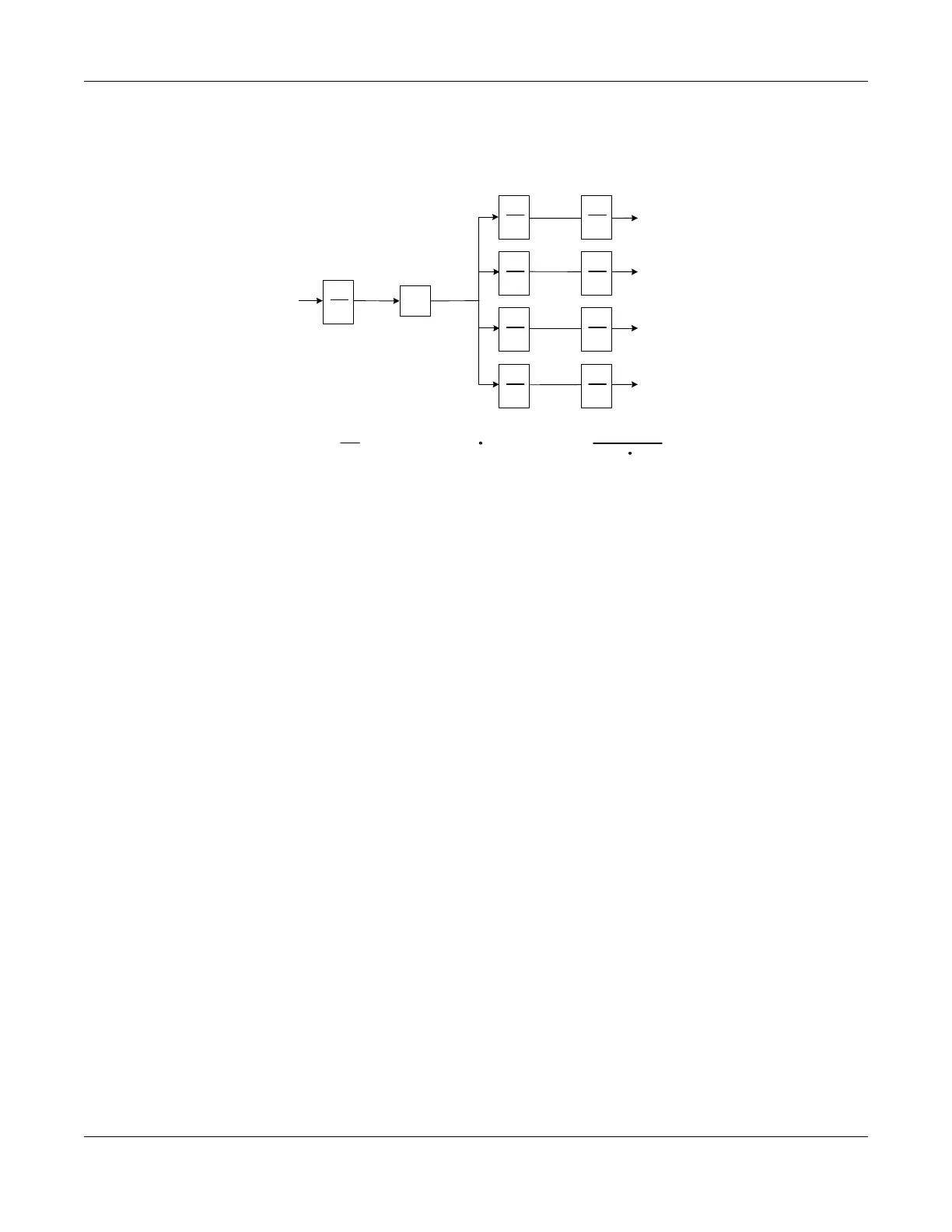
these parameters is shown in Figure 3.
Figure 3. Frequency Plan Parameters
When the MS0,1,2,3 output is f
vco
/4 or f
vco
/6 the following functions are not available:
1. Frequency Increment/Decrement
2. Phase Increment/Decrement
3. Spread Spectrum
In order for an output to be at a frequency of fvco/4 or fvco/6, a bit in Register51[7:4] must be set. See the
description for these bits in "10. Si5338 Registers" on page 28. In some cases, a very slight improvement in output
jitter may be obtained by setting MSn (feedback MultiSynth) to an integer value. All the output jitter specifications in
the data sheet were based upon characterization data with a 25 MHz PFD input. In general, the higher the PFD
input frequency the lower the jitter on the output clock.
Once MSn and MSx values have been determined, they must be converted to their digital representations and
written to the appropriate registers. The conversion for these are shown in Equation 1.
1
P1*
f
in
MS
n
f
pfd
f
vco
1
MS
0
1
MS
1
1
MS
2
1
MS
3
1
R
0
1
R
1
1
R
2
1
R
3
f
out0
f
out1
f
out2
f
out3
f
outx
=
f
vco
MS
x
R
x
f
vco
= f
pfd
MSn
f
pfd
=
f
in
P
1
5MHz <= f
pfd
<= 40MHz
2.2GHz <=
f
vco
<= 2.84GHz
*or P2
f
in
is frequency from
external clock or crystal
f
pfd
is frequency at Phase/
Frequency Detector input