6 Electrical Connection
SMA Solar Technology AG
Operating manual EVCxx-10-BE-en-10 25
6 Electrical Connection
6.1 Overview of the Connection Area
6.1.1 View from Below
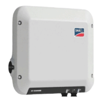
Figure 9: Bottom view of product with attached terminal cover
Position Designation
A Enclosure opening for cable gland M25 for the connection of a signal source
to the digital input
B Network port with protective cap
C Opening for cable gland M25 or M32 for connecting the utility grid
D Opening for cable gland M25 with bending protection spiral for connecting
the charging cable
6.1.2 Interior View
L1 L2 L3
N N PE
-F1
CP
L2 L3
N PE
L1
-X2
-X1
Figure 10: Connection areas in the interior of the product
Position Designation
A Terminal blocks for connecting the charging cable
B Terminal blocks for connection to the utility grid
C Terminals for connecting digital signal sources
 Loading...