HGM400 Series Genset Controller User Manual
HGM400 Series Genset Controller ISSUE 2015-05-27 Version 1.6 Page 20 of 44
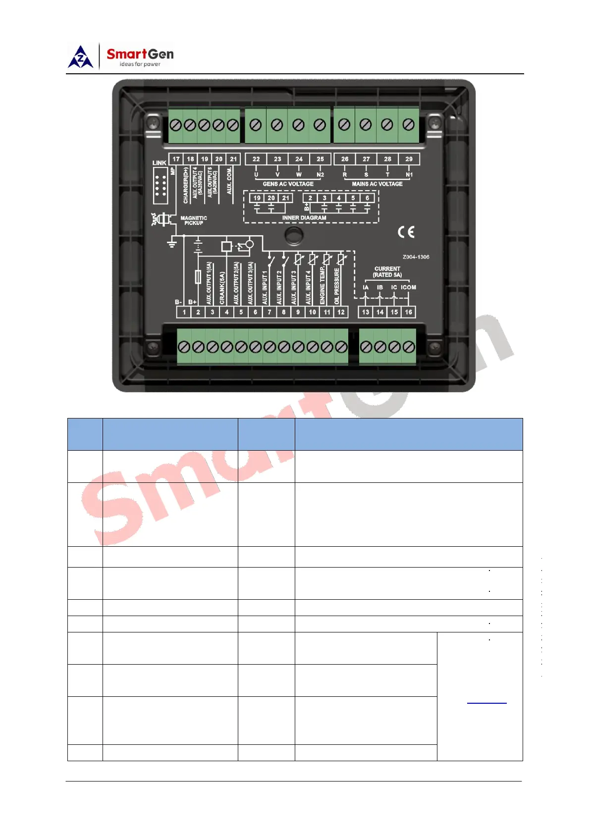
Description of terminal connections:
Connected with negative of starter
battery.
DC power supply. Connected with
positive of starter battery. If wire length is
over 30m, better to double wires in
parallel. Max. 20A fuse is recommended.
B+ is supplied by 2 point, rated 5A.
Crank Relay Output; B+ is supplied by 2
point, rated 5A. Connect to starter coil.
B+ is supplied by 2 point, rated 5A.
B+ is supplied by 2 point, rated 5A.
Ground connected is
active (B-)
Ground connected is
active (B-)
Ground connected is
active (B-); Can be used
as Level Sensor.
 Loading...