Do you have a question about the Smartgen HGM9520N and is the answer not in the manual?
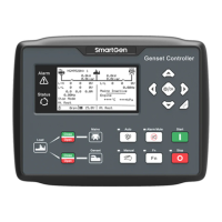
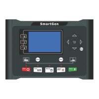
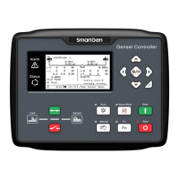
Describes the function and appearance of indicator lamps on the controller.
Details the function and icons of all pushbuttons on the controller interface.
Explains the main display screens and their content for monitoring genset status.
Outlines the automatic sequence for starting and stopping the genset.
Lists and describes all warning alarm types and their conditions.
Lists and describes all block alarm types and their conditions.
Lists and describes all shutdown alarm types and their conditions.
Provides a comprehensive list and scope of all programmable parameters available.
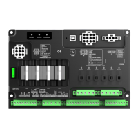
Explains how to define and configure digital output ports for various functions.
Details the various types and functions that can be assigned to digital input ports.
Outlines the initial steps for debugging a single genset unit.
Details the procedure for manual parallel operation without load.
Explains the steps for automatic parallel operation of gensets.
Configures the genset to output pre-set active power, reactive power, or power factor.
Describes the Automatic Mains Failure (AMF) start mode.
Details controller connections for Cummins ISB/ISBE engines.
Details controller connections for Volvo EDC4 engines.
Details controller connections for Yuchai engines.
| Frequency | 50/60Hz |
|---|---|
| Display | LCD |
| Input Voltage | DC 8-35V |
| Operating Temperature | -20°C to +70°C |
| Communication Interface | RS485 |