-9-
No.EX##-OMN0036
System Outline
•System configuration
The EX600 range of units can be connected to various types of Fieldbus to realize the reduction of input or
output device wiring and the distributed control system. The unit communicates with the Fieldbus through
the SI unit. One SI unit can be connected with manifold valves with up to 32 outputs and the input • output •
I/O units with maximum 10 units.
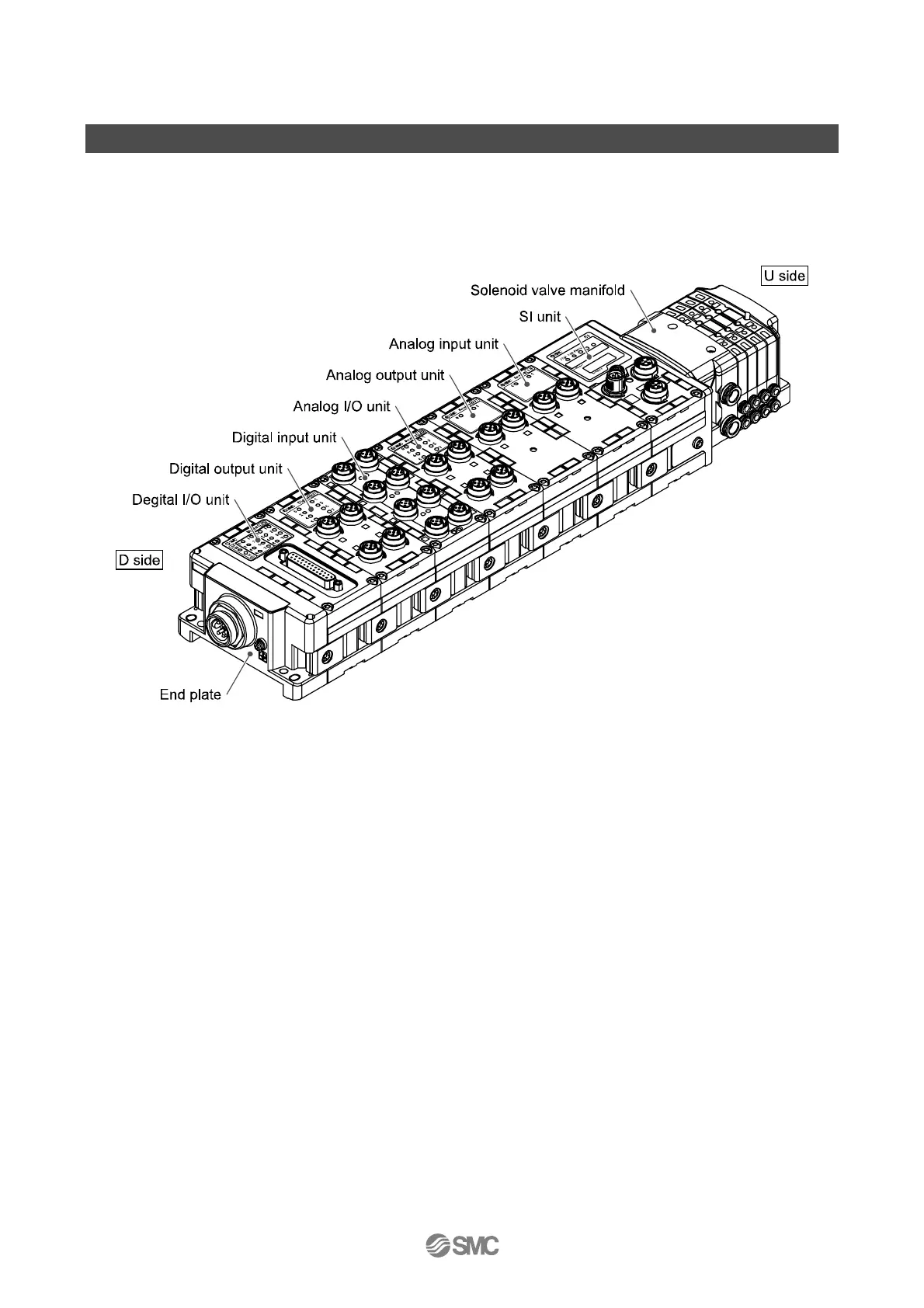
SI unit: Performs Fieldbus communication and solenoid valve manifold ON/OFF output.
Digital input unit: For connecting sensors with switch output capability. PNP and NPN types are available.
Digital output unit: For connecting output device such as solenoid valves, lamps, buzzers, etc. PNP and
NPN types are available.
Digital I/O unit: This unit has both digital input and output functions. PNP and NPN types are available.
Analog input unit: For connecting sensors with analog output capability.
Analog output unit: This can be connected to the equipment which can read analog input.
Analog I/O unit: This unit has both analog input and output functions.
End plate: Connected at EX600 Manifold’s D side, incorporating the power supply connection.
Solenoid valve manifold: An assembly of solenoid valves. One connector is used as the electric connection
to all connected valves.
 Loading...


