-43-
No.EX##-OMN0036
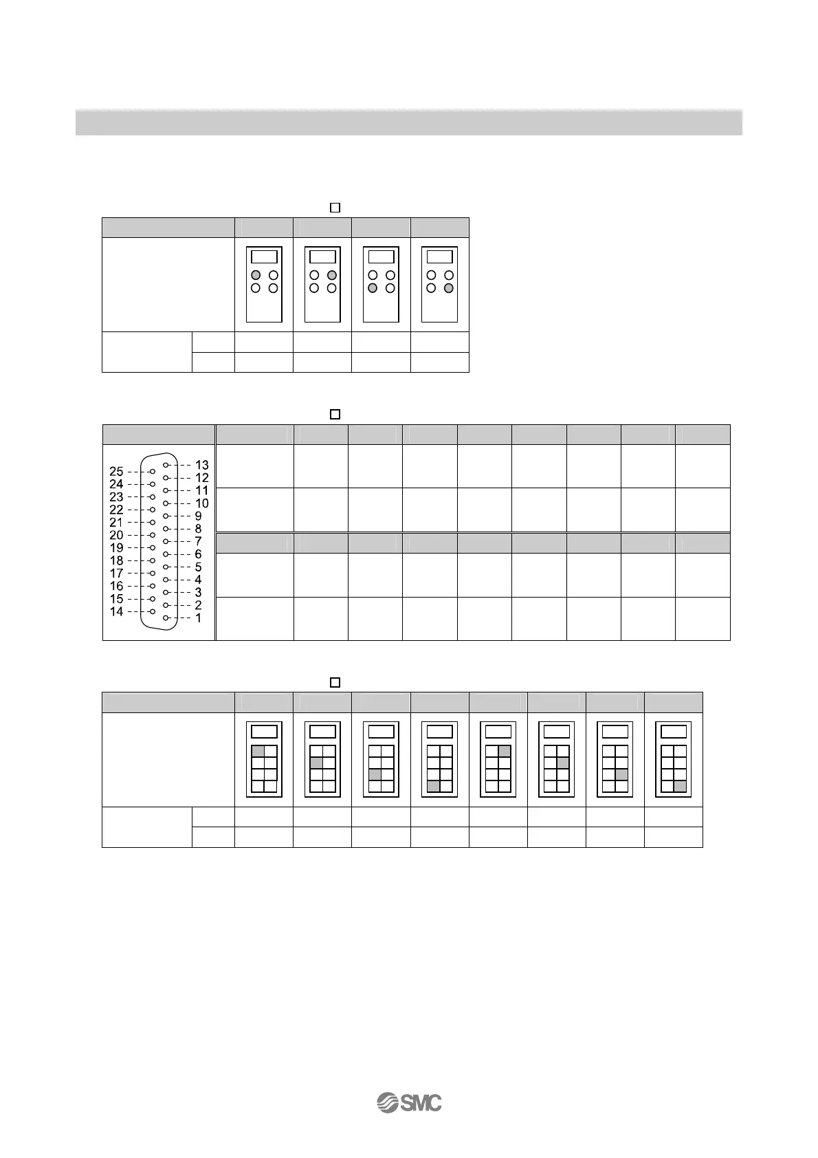
○Digital Output data
The relationship between the connector position and the output data assignment is as shown in the table
below.
•Output signal assignment (EX600-DY B)
Connector number 0 1 2 3
Connector position
Pin 2 Bit 1 Bit 3 Bit 5 Bit 7
Output signal
Pin 4 Bit 0 Bit 2 Bit 4 Bit 6
•Output signal assignment (EX600-DY E)
Configuration Pin number 1 2 3 4 5 6 7 8
Signal
name
Output
0
Output
2
Output
4
Output
6
Output
8
Output
10
Output
12
Output
14
Output
signal
Bit 0 Bit 2 Bit 4 Bit 6 Bit 8 Bit 10 Bit 12 Bit 14
Pin number 14 15 16 17 18 19 20 21
Signal
name
Output
1
Output
3
Output
5
Output
7
Output
9
Output
11
Output
13
Output
15
Output
signal
Bit 1 Bit 3 Bit 5 Bit 7 Bit 9 Bit 11 Bit 13 Bit 15
•Output signal assignment (EX600-DY F)
Group 0 1 2 3 4 5 6 7
Terminal position
Pin 2 Bit 0 Bit 2 Bit 4 Bit 6 Bit 8 Bit 10 Bit 12 Bit 14
Output signal
Pin 4 Bit 1 Bit 3 Bit 5 Bit 7 Bit 9 Bit 11 Bit 13 Bit 15
 Loading...


