- 7 -
①
Proceed carefully, as incorrect wiring can cause damage.
②
Use a DC power supply with sufficient capacity and a low ripple.
③
Turn off the power supply to remove and insert the connector.
④
Never rotate the right angled type connector as it is not designed to rotate.
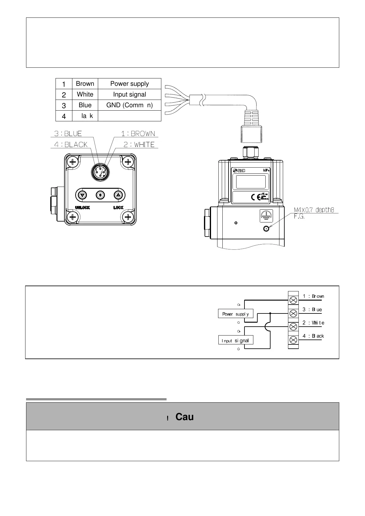
(Note) The wire colour is shown
for when an alternative cable is used.
Current / Voltage type(ITVX2030-0, ITVX2030-1, ITVX2030-2, ITVX2030-3)
Power supply 24 VDC
Input signal 4~20mADC (ITVX2030-0)
0~20mADC (ITVX2030-1)
0~ 5VDC (ITVX2030-2)
0~10VDC (ITVX2030-3)
Wiring diagram(
((
(Monitor output)
))
)
△
△△
△
,
!
!!
!
Caution
When the monitor output is not being used, prevent the unused wires from touching the other
wires, as this can cause a malfunction.
Power suppl y
I nput
si gnal
1:
Br own
3:
Bl ue
2:
Whi t e
4:
Bl ack
○
+
○
-
○
+
○
-
1
Brown Power supply
2
White Input signal
3
Blue GND (Common)
4
Black Monitor output

 Loading...