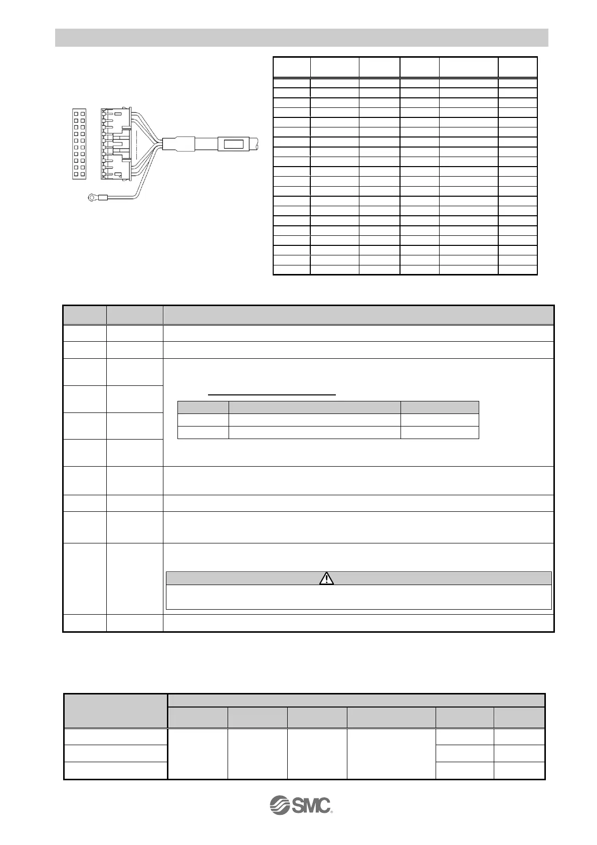
6.3 The parallel I/O signal is detailed
Connected to the cable shield Be sure to
provide grounding.
A dot mark in a specific colour is printed on each cable.
- Input terminal-
The terminal for the 24V of the 24 VDC I/O signal power.
The terminal for the 0V of the 24 VDC I/O signal power.
Assignment of the function depends on the parameter which determines the method for inputting
the pulse signal (Basic parameter “Option1”)
Refer to “7.2 Basic parameter (page 33)”for details.
Normal (CW) or reversed (CCW) pulse.
Reverse (CCW) or normal (CW) pulse.
For 2 pulse type, PP is for normal rotation (CW), and NP is for reversed rotation (CCW) as
initial setting.
Command to Return to origin. Returning to home position starts when turned on while the servo
is ON.
Resets alarm. Alarm output is OFF when RESET is ON while alarm is generated.
Specify the servo ON.When SVON is ON, the servo motor will be turned ON. When this is OFF,
the servo motor will be turned OFF.
*1)
Deviation reset signal.Signal to reset the difference between the movement
commanded by the pulse signal and the actual movement.
1. Clear the deviation counter when CLR is turned ON from OFF. (Recognized by the edge)
2. The electric actuator does not operate when the pulse is input while CLR is ON.
Signal to switch to pushing operation. When TL is ON, it becomes pushing operation
*1) When power is applied,it may take up to 10 seconds (max.20 sec.) from SVON input to SVRE output
depending on the electric actuator position.
Valid condition of parallel I/O (ON: Only ON is recognized, OFF: Only OFF is recognized, ON/OFF:
Recognized regardless of ON or OFF)
Input signal with
Reception condition
Returning to home
position
Other than during
operation
 Loading...