EasyManuals Logo
Home>SMC Networks>Industrial Electrical>LECPA Series

SMC Networks LECPA Series User Manual

Default Icon
109 pages
To Next Page IconTo Next Page
To Previous Page IconTo Previous Page
Page #36 background imageLoading...
Page #36 background image
- 35 -
TL
COM+
COM-
NP+
NP-
PP+
PP-
SETUP
RESET
SVON
CLR
1
2
3
4
5
6
7
8
9
1
0
11
1
2
WAREA
1
3
BUSY
1
4
SETON
1
5
INP
1
6
SVRE
1
7
*ESTOP
1
8
*ALARM
1
9
2
0
Pulse
Input
Circuit
Pulse
NP+
NP-
PP+
PP-
3
4
5
6
Direction
Pulse
Differential input of 2 pulse mode
Differential input of 1 pulse mode
NP+
NP-
PP+
PP-
3
4
5
6
NPN open collector input for 2 pulse mode
*1)
Pulse
Equivalent to line driver DS26C31T
Power supply for pulse
signal
24VDC or 5VDC
NP+
NP-
PP+
PP-
3
4
5
6
Pulse
Pulse
24 VDC
Pulse
NP+
NP-
PP+
PP-
3
4
5
6
Direction
R
R
R
R
Load
Load
Load
Load
Load
Load
Load
Load
Power supply for pulse
signal
24 VDC or 5 VDC
AREA
TLOUT
Load
NPN open collector input for 1 pulse mode
*1)
6.4 Parallel I/O Wiring Example
When you connect a PLC, etc. to the CN5 parallel I/O connector, please use the I/O cable.
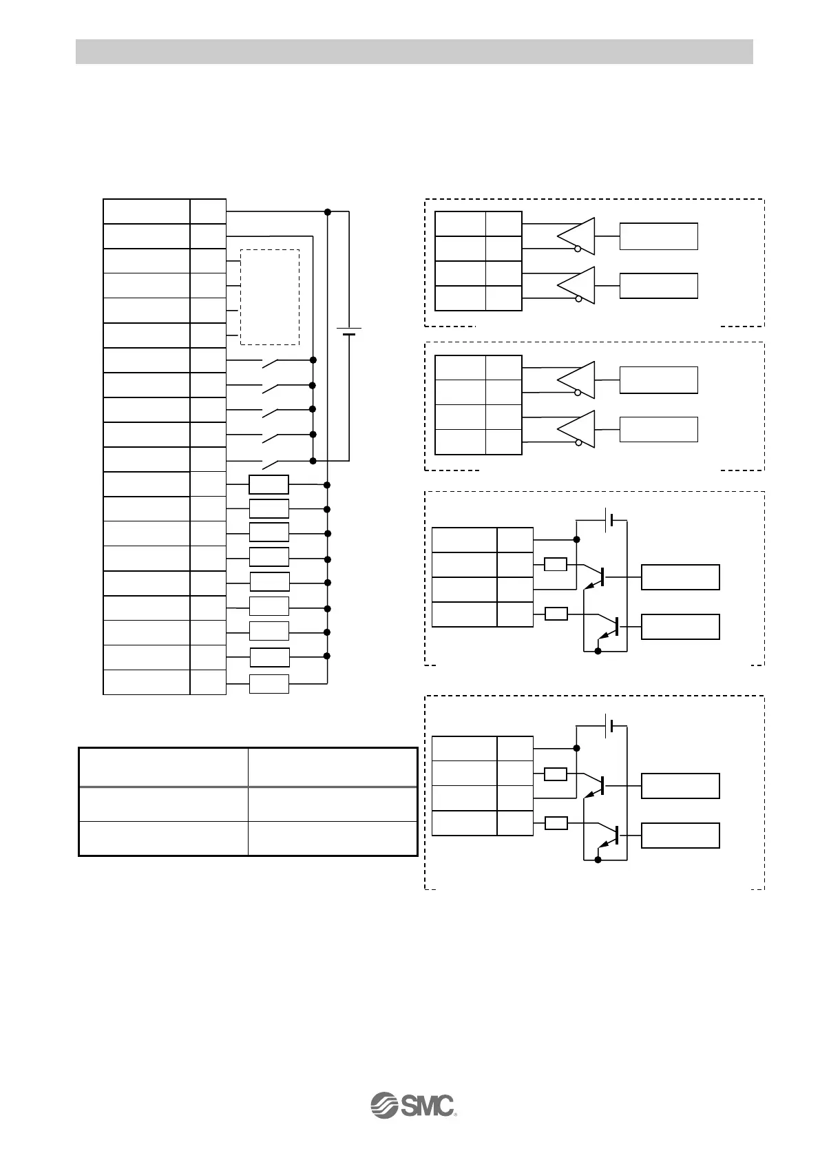
Wiring depends on the driver parallel input/output (NPN, PNP) and input pulse mode.
NPN typeLECPAN□□-□
Pulse input circuit
R: Current limiting resistor
*1) The pulse input circuit of NPN type and PNP type is the same.
Refer to the pulse input circuit of PNP type
LECPAP□□-□
for the connection of PNP open collector
.
Power supply voltage
For pulse sign
Current limiting resistor
R type
24 VDC±10%
3.3kΩ±5%
0.5W or more
5 VDC±5%
390Ω±5%
(0.1W or more)

Table of Contents

Questions and Answers:

Question and Answer IconNeed help?

Do you have a question about the SMC Networks LECPA Series and is the answer not in the manual?

SMC Networks LECPA Series Specifications

General IconGeneral
BrandSMC Networks
ModelLECPA Series
CategoryIndustrial Electrical
LanguageEnglish