-12-
No.PF※※-OMO0012-D
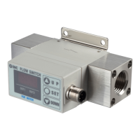
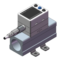
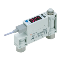
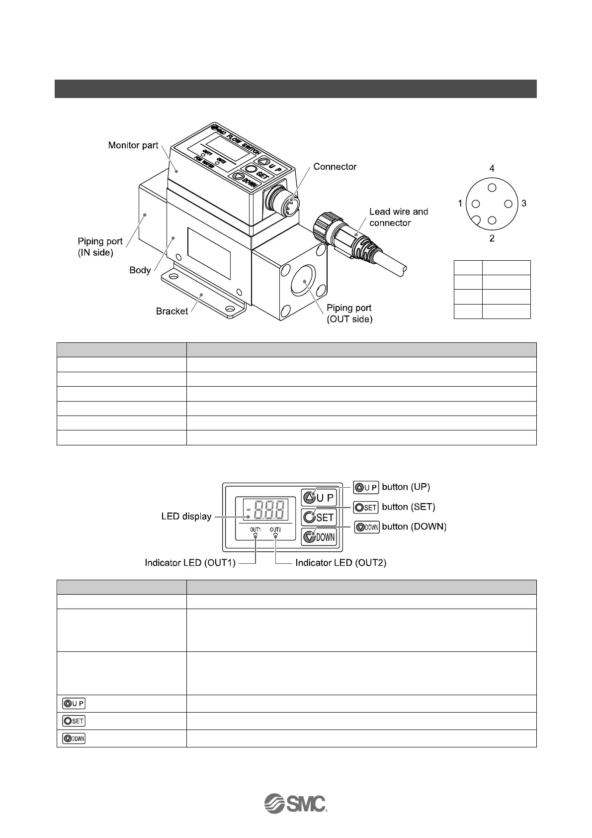
Summary of Product parts
Body
Connector pin
numbers
(On the product)
Connected to the fluid inlet at IN side and to the fluid outlet at OUT side.
Bracket for mounting the product.
Connector for electrical connections.
Lead wire to supply power and transmit output signals.
Displays the flow value, setting mode, and error indication.
Indicates the output status of OUT1. LED is ON (Green) when OUT1 is ON.
The LED flashes when an over current error occurs.
When the accumulated pulse output mode is selected, the indicator LED will turn OFF.
Indicates the output status of OUT2. LED is ON (Red) when OUT2 is ON.
The LED flashes when an over current error occurs.
When the accumulated pulse output mode is selected, the indicator LED will turn OFF.
Selects the mode or increases the ON/OFF Set value.
Press this button to change to another mode and to set a value.
Selects the mode or decreases the ON/OFF Set value.
 Loading...