-18-
No.PF※※-OMO0012-D
■Wiring
Connections should only be made with the power supply turned off.
Use separate routes for the product wiring and any power or high voltage wiring. Otherwise, malfunction
may result due to noise.
Ensure that the FG terminal is connected to ground when using a commercially available switch-mode
power supply. When a switch-mode power supply is connected to the product, switching noise will be
superimposed and the product specification can no longer be met. This can be prevented by inserting a
noise filter, such as a line noise filter and ferrite core, between the switch-mode power supply and the
product, or by using a series power supply instead of a switch-mode power supply.
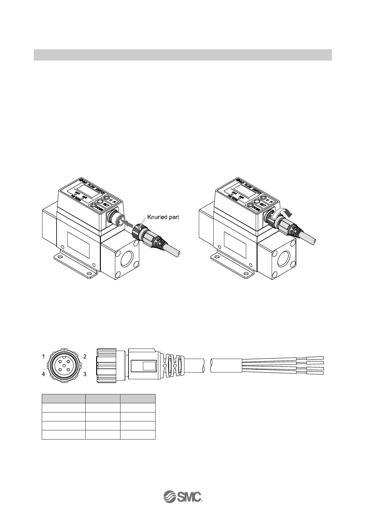
●Connecting the wiring
Align the lead wire connector with the connector key groove, and insert vertically.
Connection is complete when the knurled part is fully tightened. Check that the connection is not loose.
●Connector Pin numbers
When the lead wire with connector designated for the PF2W7 is used, the wire colours will apply as shown
in the diagram.
Connector Pin numbers (on the lead wire)
 Loading...