Servodrives / inverters series COSMOS 301X Installation, use and maintenance manual - EN
5.7.4 Connections (KZ010385)
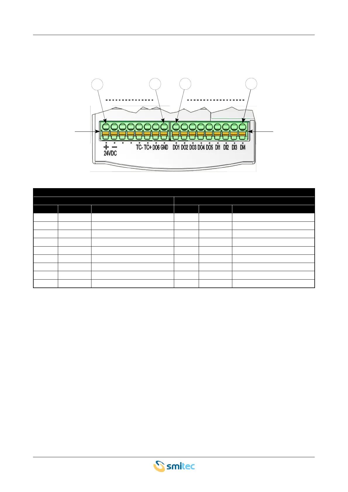
This version is equipped with two removable connectors (J5 and J6) for wiring 24V auxiliary power and
digital/analogue I/Os. Here is the pin configuration of the connectors:
24V and I/O power
connector J5 connector J6
pin label signal pin label signal
1 24VDC + 24VDC power – positive side 1 D01 Digital output #1
2 24VDC - 24VDC power – negative side 2 D02 Digital output #2
3 - NC 3 D03 Digital output #3
4 - NC 4 D04 Digital output #4
5 TC- thermocouple J input - negative 5 D05 Digital output #5
6 TC+ thermocouple J input - positive 6 DI1 Digital input #1
7 D06 Digital output #6 7 DI2 Digital input #2
8 GND Earth on digital I/Os 8 DI3 Digital input #3
9 DI4 Digital input #4
Ver. 1.09 SMITECdd 44/74