Chapter 7 – Prestart Inspection
A46JRT – 0260996 33
2. Visually inspect the slide pads to make sure they are
securely fastened to the main boom.
3. Inspect the surface where the pads contact the tip
boom. The paint must be in place with no signs of
bare metal.
Fasteners
To inspect the component fasteners:
1. Visually inspect all fasteners to see that none are
missing or loose.
2. Inspect all of the bolts, nuts, roll pins, collars, and
snap rings that connect the booms and cylinders.
They should all be present, tight, and not damaged
in any way.
3. Raise the riser boom to access the inner race ro-
tation bearing bolts in the turntable (refer to Figure
7.12). The outer race bolts can be viewed through
the openings in the turntable. Rotate the turntable to
inspect all of the outer race bolts.
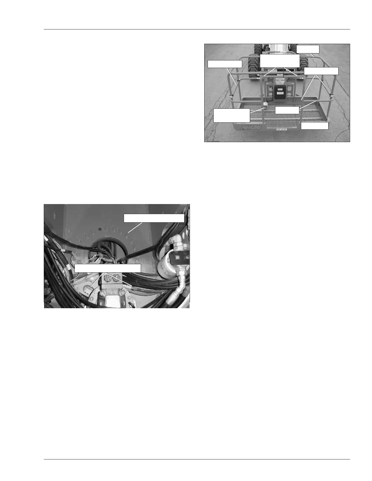
Figure 7.12 – Rotation Bearing Bolts
4.
Inspect the inner and outer race rotation bearing bolts
to ensure that none are missing, damaged, or loose.
Upper Control Station
Inspect the platform and upper controls, after verifying all
functions operated properly from the lower controls.
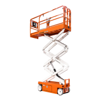
Guardrail System
The guardrail system includes (refer to Figure 7.13):
• A top rail
• A mid rail
• Three entry gates: one on each side and one rear
• Toeboards around the sides of the platform.
Figure 7.13 – Guardrail System
To inspect the guardrail system:
1. Visually inspect all components of the guardrail
system. Make sure the rails and toeboards are all in
place and free of any damage or deformation.
2. Visually inspect the rail and toeboard welds for cracks.
3. Visually inspect all bolts and nuts fastening the plat-
form in place. They must be present and not show
any signs of looseness.
4. Inspect the gates to be sure they are present, are not
damaged, and move freely.
Fall Protection Anchors
There are two fall protection anchors below the upper
control panel (refer to Figure 7.13).
To inspect the anchors:
1. Visually inspect the fall protection anchors to make
sure they are in place and are not deformed.
2. Look for visible cracks in the welds and at the weld
to parent material joints. A bright light may be used
to provide adequate visibility of the inspection area.
Operating Controls
Use the following procedure to operate the machine from
the upper controls:
1. Turn the battery disconnect switch on.
2. At the lower controls, pull the emergency stop switch
outward to the on position. Place the controls switch
in the upper control position.
3. At the upper controls (refer to Figure 7.14), pull the
emergency stop button outward.
Rotation Bearing Bolts
Outer Race Access Holes
Toeboard
Platform Foot
Switch
Top Rail
Mid Rail
Gravity Gate
Gravity Gate
Fall Protection
Anchors