Chapter 7 – Prestart Inspection
A46JRT – 0260996 35
• If the power was off, push the reset button to
restore power.
• If the power was on, repair or replace the recep-
tacle.
Level Sensor
Use the following procedure to test the level sensor:
Danger
The aerial platform can tip over if it becomes unsta-
ble. Death or serious injury will result from a tip-over
accident. Do not drive an elevated aerial platform on
soft, uneven, or sloping surfaces. Do not drive the
machine on grades that exceed 25 percent.
1. With the machine in the stowed position, drive on
a grade that is between 5 and 10 degrees. Stop to
ensure the brakes engage.
2. Extend the tip boom about 2′ (60 cm).
3. Verify that the tilt alarm sounds and the tilt warning light
on the lower and upper control panels are illuminated.
Warning
The potential for an accident increases when safety
devices do not function properly. Death or serious
injury could result from such accidents. Do not alter,
disable, or override any safety device.
4. If the alarm does not sound and the warning lights
do not illuminate, remove the machine from service
until the problem is corrected.
5. Retract the tip boom and drive the machine to a
smooth, flat, level surface.
Drive Motion Alarm
The machine is equipped with a drive motion alarm.
• Operate the machine functions to ensure that the
alarm sounds to warn personnel in the area that the
aerial platform is in motion.
All Motion Alarm
The machine may be equipped with an all motion alarm.
• Operate machine functions to ensure that the alarm
sounds to warn personnel in the area that the aerial
platform is in motion.
Sandblast Protection Kit
The optional sandblast protection kit protects the cylinders
from abrasion while sandblasting or from paint overspray.
Rubber covers protect each cylinder rod as it extends
and retracts. The covers prevent sand and paint from
damaging the cylinder seals and rod.
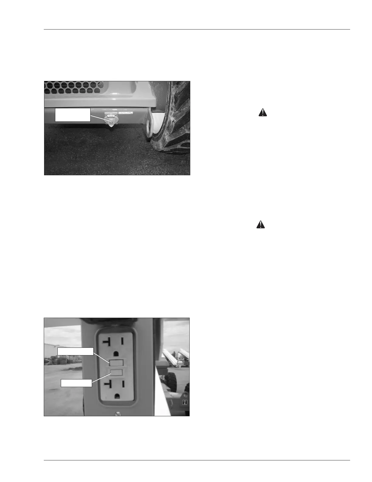
Electrical Power Outlet
Connect a source of 110 volt AC power to the power-in-
put connector on the right side of the chassis (refer to
Figure 7.15).
Figure 7.15 – Power-Input Connector
Some machines may have an electrical outlet at the
platform, but no power-input connector on the chassis. In
that case, power is supplied by an optional AC generator.
An external power source is not required.
With the engine running, place the AC generator switch
in the generator position to provide electrical power to the
electrical outlet at the platform and to the outlet on the
end of the generator housing.
Plug an electrical tool into the receptacle at the platform
and at the generator and try to operate the tool to verify
proper operation of the outlet.
The outlet is equipped with a ground fault circuit interrupter
(GFCI). Use the following procedure to test the GFCI.
1. Push the test button (refer to Figure 7.16).
Figure 7.16 – Electrical Power Outlet
2. Plug an electrical tool into the outlet and verify the
power is off.
Power-Input
Connector
Test Button
Reset Button