Chapter 8 – Prestart Inspection
S1930E/S1932E/S2632E – 1360460 25
Caution
Not all hydraulic uid is suitable to use in the hy-
draulic system. Some have poor lubricating char-
acteristics and may increase component wear. Only
use hydraulic uid as recommended.
3. If necessary, add uid of the proper type.
Note
Refer to Chapter 2 for the proper type and grade of
hydraulic uid to use. The need to regularly add uid
indicates a leak that should be corrected.
4. Replace the cap making sure it is tightly in place.
Hoses, Tubes, and Fittings
To inspect the hoses, tubes and ttings:
1. Inspect all hydraulic hoses, tubes, and ttings for
wear, leakage, or damage (refer to Figure 8.7).
Figure 8.7 – Hoses, Tubes, and Fittings
2. Make sure the hoses are properly routed to avoid
sharp edges, kinking, and scufng.
3. Inspect the tubes for dents or other damage that may
restrict uid ow.
4. Make sure all hoses and tubes are held rmly in their
support brackets.
5. Check under the chassis for uid that has leaked. Hy-
draulic uid leaks are easily visible on the ground.
Free-Wheeling Valve
The free-wheeling valve is located on the hydraulic mani-
fold in the hydraulic tray. Check the free-wheeling valve
to make sure it is fully closed (clockwise).
3. Using the lower controls completely lower the plat-
form.
Cables and Wiring Harness
To inspect the cables and wiring harness:
1. Visually inspect all cables and wiring for wear and/or
physical damage such as loose connections, broken
wires, and frayed insulation.
2. Check the wiring in areas where a change in routing
direction may cause them to become pinched.
3. Make sure the cables and wires are properly routed
to avoid sharp edges, pinching, and scufng.
Hydraulic System
Hydraulic power is supplied from a single stage hydraulic
pump with a 4.25 horsepower DC electric motor.
Danger
Hydraulic uid escaping under pressure can have
enough force to inject uid into the esh. Serious
infection or reaction will result if medical treatment is
not given immediately. In case of injury by escaping
hydraulic uid, seek medical attention at once.
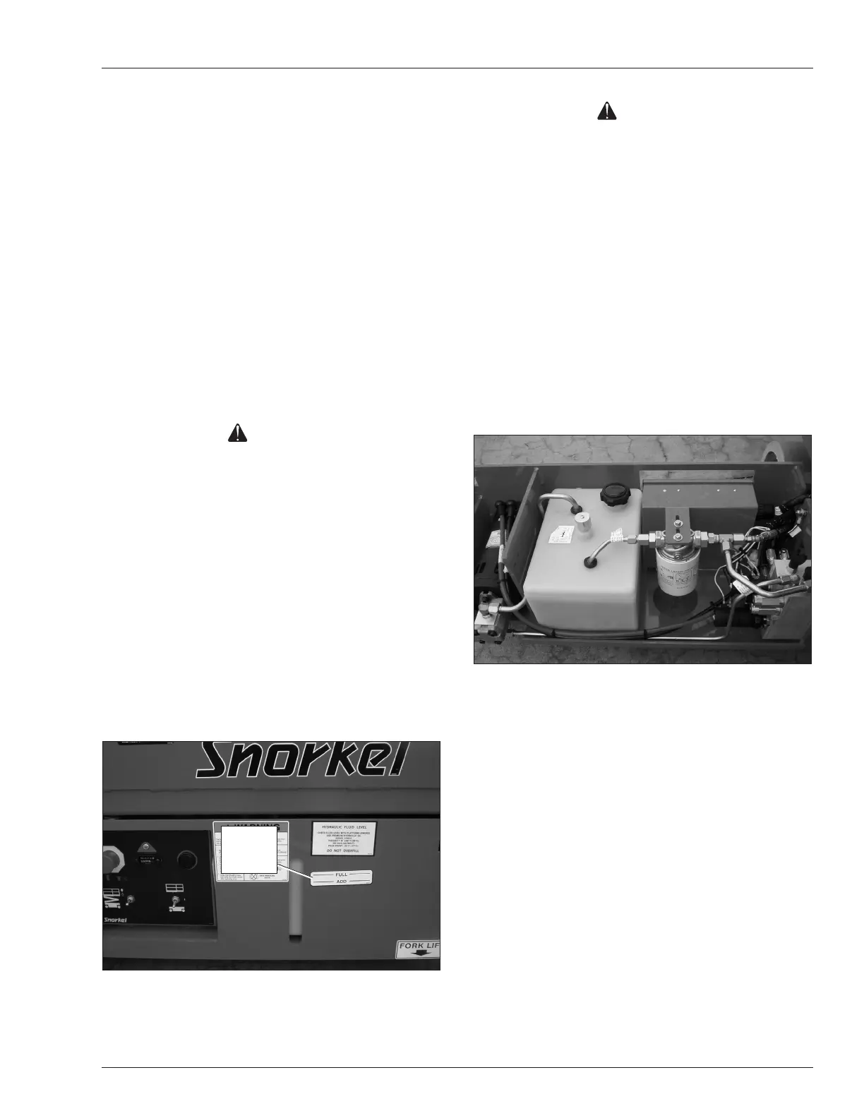
The hydraulic reservoir, pump, lter, and control valve
are located in the hydraulic tray on the right side of the
chassis.
Fluid Level
To inspect the uid level:
1. Make sure the aerial platform is fully stowed on a
level surface.
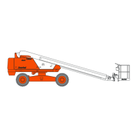
2. The uid level must be between the add and full
marks (refer to Figure 8.6).
Figure 8.6 – Hydraulic Tray
Fluid
Level
Indicator