15
iPDU - Ref.: IOMPDUXXXX02-GB 00
ENGLISH
3. GETTING STARTED
DIP Switch Setting Table for Daisy Chain ID in Manual mode
DIP 1 DIP 2 DIP 3 DIP 4 Daisy Chain ID
OFF OFF OFF OFF 15
OFF OFF OFF ON 14
OFF OFF ON OFF 13
OFF OFF ON ON 12
OFF ON OFF OFF 11
OFF ON OFF ON 10
OFF ON ON OFF 9
OFF ON ON ON 8
ON OFF OFF OFF 7
ON OFF OFF ON 6
ON OFF ON OFF 5
ON OFF ON ON 4
ON ON OFF OFF 3
ON ON OFF ON 2
ON ON ON OFF 1
ON ON ON ON 0
Down: ON ; Up: OFF
Manual mode: Use DIP switches on the front panel to set the (daisy chain) ID number for each iPDU that you add to the chain.
You may set Daisy Chain ID for the first unit (Master) to 0 (DIP Switches: On, On, On, On) and the ID for the
second unit (Slave 01) to 1(DIP Switches: On, On, On, OFF), etc. The DIP Switch Setting Table for Daisy Chain
ID is described in the following table.
3. After all the iPDUs have been set up, power up all the iPDU IIs.
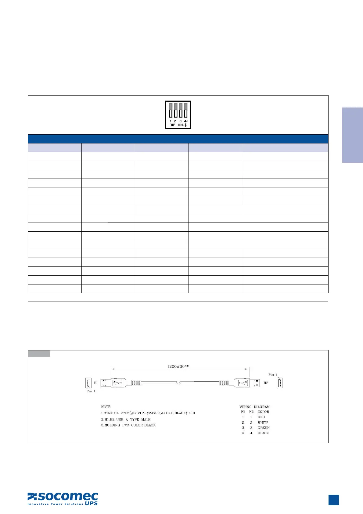
Note: The total length of all USB cables in the chain must not exceed 8 metres. The USB cable specification is illustrated
in the following diagram.
3.11-2