14
iPDU - Ref.: IOMPDUXXXX02-GB 00
3. GETTING STARTED
3.11. Daisy Chaining
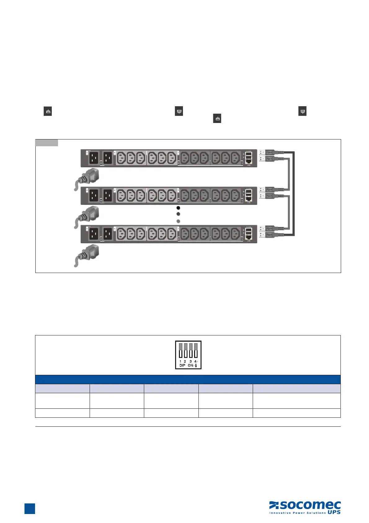
To manage more devices, up to 5 additional iPDUs can be daisy chained to the first unit. Follow instructions below to set up a daisy
chain installation.
1. For each iPDU that you add to the chain, use USB cables to connect it to the parent iPDU’s C-Link Port. The upper C-Link port
(
) of child iPDU II is connected to lower C-Link port ( ) of its parent iPDU II and the lower C-Link port ( ) of the lowest
level iPDU II is connected to the highest level parent’s upper C-Link port (
) to form a cyclic (ring) structure as illustrated in the
following diagram
2. The daisy chain installation can operate in Auto mode or Manual mode. Use daisy-chaining mode DIP switch (C-link DIP) to set
the operation mode.
Auto mode: For the master iPDU, set all the DIP switches of the C- link to ON by moving all the switches downwards; for all the
other iPDUs (slave iPDU IIs) in the daisy chain, set all the DIP switches of the C- link to OFF by moving all the switches
upwards. After setting the DIP switches for all the iPDUs in the daisy chain, the daisy chain ID can be assigned for
each iPDU automatically.
3.11-1
DIP Switch Setting Table for Daisy Chain ID in Auto mode
DIP 1 DIP 2 DIP 3 DIP 4 Daisy Chain ID
OFF OFF OFF OFF
Slave01 to Slave05, automatically
assigned by iPDU
ON ON ON ON Master
Down: ON ; Up: OFF