8
iPDU - Ref.: IOMPDUXXXX02-GB 00
2. INTRODUCING iPDU
4
1
2
3
A B C D E F G H I J K L
A B C D E F G H I J K L
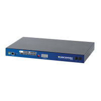
2.3-3
Rear Panel of 2-inlet Model
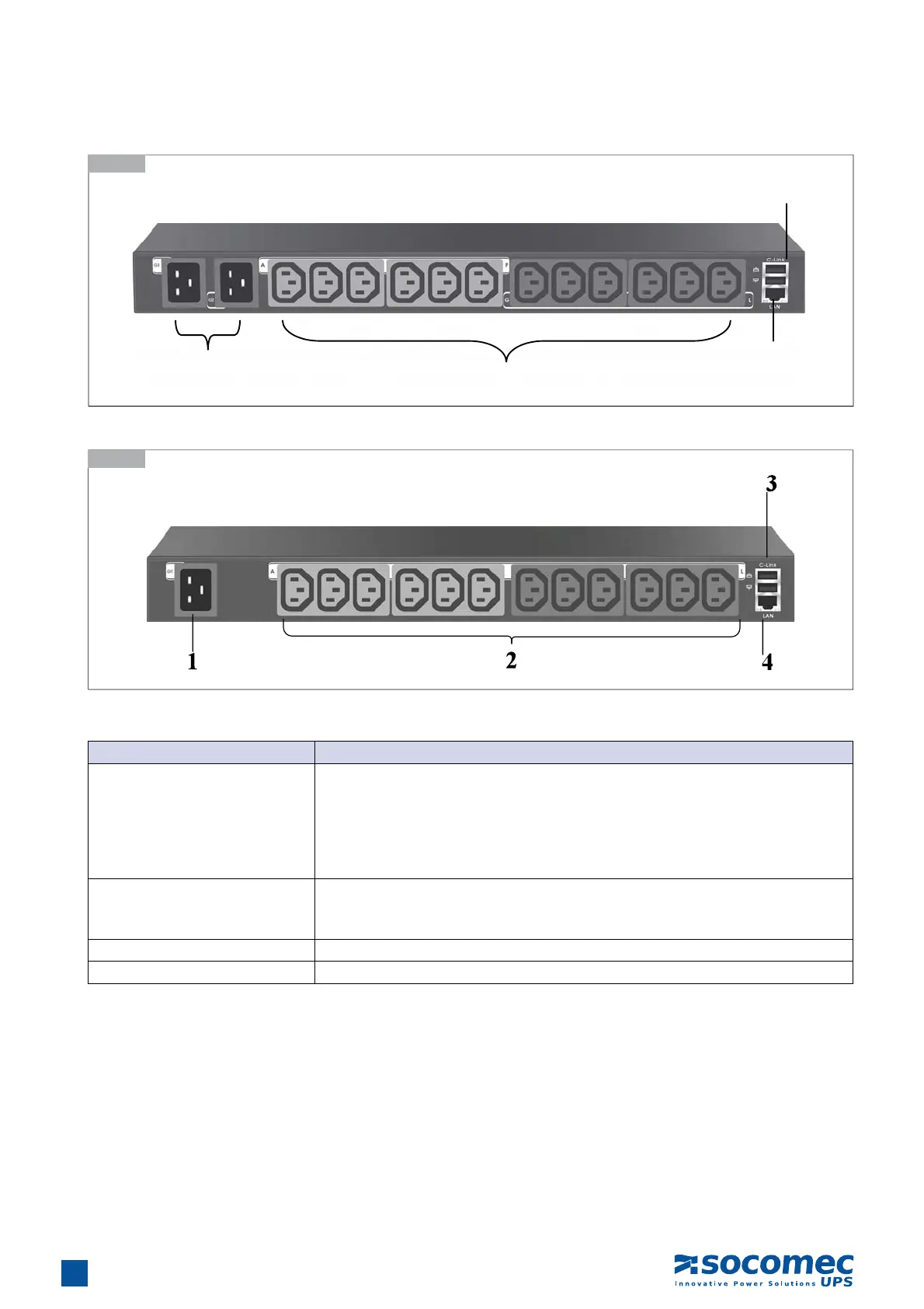
2.3-4
Rear Panel of 1-inlet Model
Component Description
1. Input power (G1 ~ G2)
Connects to a power outlet
2-inlet model:
• G1 supplies power to outlet A to F
• G2 supplies power to outlet G to L
1-inlet model:
• G1 supplies power to outlet A to L
2. Power Outlet(A ~ L)
Connects a device to each power outlet to supply it with power.
Note: Three outlets group into one unit and the maximum load is 10 Amps for one
unit or one outlet.
3. Daisy-chaining (C-link) port Enables users to cascade next iPDU II through an USB cable.
4. Ethernet (LAN) port Enables users to configure the iPDU through a LAN or WAN