22
PSX-NL4 Network Module - Operation Manual
Available Parameters of A PSX Power Supply
Any PSX power supply connected to a device input will provide the following parameters (Figure 3.2, page 21):
Device This is the identifying label for the PSX device. This label is given by the PSX-NL4 and is not user settable.
The first PSX connected to a device input is labeled FP1 and the second is labeled FP2. Up to two PSX
power supplies may be connected to an PSX-NL4 board.
Model This is the model family of the PSX connected to the PSX-NL4 as reported by the PSX. There are currently
three power model families: FPO75, FPO150, and FPO250.
Output Voltage This is the measured system output voltage (in Volts DC) of the PSX, as measured directly out of the
power supply engine within the PSX power supply board. This voltage is distributed to the DC1 and DC2
output terminals and fastons.
AC Fault Status Indicates whether the PSX is reporting a low or missing AC voltage. "No" on a green background indicates
that no problem is being reported. "Yes" on a yellow background indicates an AC Fault condition. See the
PSX manual to troubleshoot.
System Fault Status Indicates whether the PSX is reporting a System Fault condition. "No" on a green background indicates
that no problem is being reported. "Yes" on a yellow background indicates a System Fault condition. See
the PSX manual to troubleshoot.
Battery Voltage Indicates the measured battery voltage in Volts DC. This field only indicates the terminal voltage of the bat-
tery set and does not necessarily indicate the condition or state of charge of the battery set.
Battery Chg Current This field indicates the rate of charge the PSX is applying to the battery set (in Amps DC). This field only
represents charge into the battery and does not show battery discharge current. Use the PSX-NL4 current
sensor to measure both charge and discharge current.
FAI Status This field indicates the status of the FAI Input of the PSX. "Inactive" on a green background indicates that
the FAI input is not activated. "Active" on a red background indicates that the FAI input is receiving a valid
activation signal.
FAI Latch This field indicates the status of the FAI Latch Input of the PSX. If the Latch Input is being used and the
FAI Input is active and latched, this field will show "Active" on a red background. If FAI Latch is not being
used this field will show "Inactive" on a green background.
AC Fault Count This field shows the number of AC Fault detections since the last fault counter reset. When new, a PSX
may contain a random number in this field and the counter should be reset (in the FPO Service Settings
section) before being used.
System Fault Count This field shows the number of System Fault detections since the last reset of the fault counter. A PSX
may contain random data in this field when new and the counter should be reset (in the FPO Service Set-
tings section) before being used.
Battery Installed Time This field displays the battery runtime in hours since the last reset of the battery runtime counter. The
battery runtime field may display random data on a new PSX and should be reset on the FPO Service
Settings section before use. This Runtime is independent of the Battery End-of-Life / Bat. Replacement
Date calculation.
System Installed Time This field displays the total power-up time in hours for the PSX. This value cannot be reset. It is normal
for several hours to show in this field on a new PSX, due to burn-in testing at the factory.
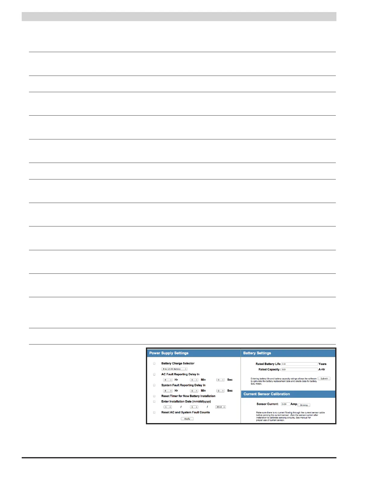
3.2.1.2 PSX Power Supply Settings
The section at the bottom left of the PSX home
screen will show the programmable settings for
the PSX power supply.
(Figure 3.3)