RM-4E Components
10
Method B - via RS-485 (RM Bus Connector)
Connect +12 VDC to Pin 1 of the RS-485 connector on the bottom
right side.
Connect Ground (Gnd) to Pin 4 of the RS-485 connector.
NOTE The +12 VDC input on Pin 1 has a protection diode that prevents you
from using the RS-485 connector as a source of +12 VDC if you power
through the Power IN connector.
Battery
Connect the plus and minus sides of the 12 VDC battery to the Battery
connector. The battery provides power for memory retention in the event
of a power failure. When power is restored, the battery is charged by the
power supplied through the Power In connector.
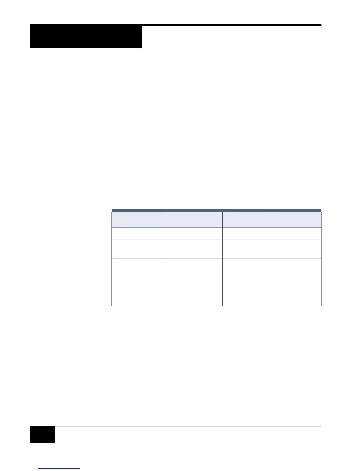
LED Connector Table 2 lists LED Connector Signals and Functions on the RM-4E board.
NOTE UL has not evaluated using Pin 5 to drive an external beeper.
Typical LED Scenarios
One wire Bi-Color - Attach the brown wire from the read head to the
Yellow LED drive on the RM-4E.
Two wire Red and Green - Attach the brown wire from the read
head to Red LED drive. Attach the orange wire from the read head to
the Green LED drive.
Three wire Red, Green, Yellow - Attach each LED drive to the
associated color LED.
See “LED Control” on page 22 for information.
TABLE 3. LED Connector Signals and Functions
Pin Signal Function
6 Gnd Ground
5 Beep Used to drive an external beeper on a
reader connected to the unit.
4 Grn Green LED drive
3 Yel Yellow LED drive
2 Red Red LED drive
1 +5 VDC + 5 VDC, if required