Lock Wiring Configurations
13
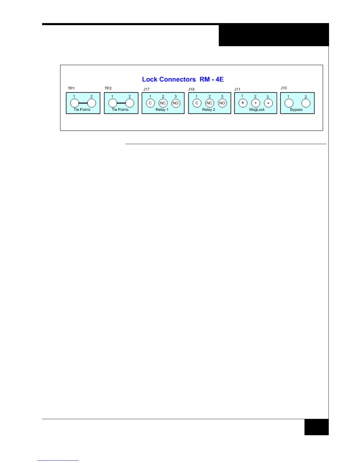
FIGURE 7. Lock Connectors
LOCK WIRING
CONFIGURATIONS
RM-4E lock connectors support the following wiring configurations:
Magnetic Lock using Relay 2
Electric Strike using Relay 2
Electric Strike using Relay 1
The following sections describe how to connect each configuration. The
electric strike examples are shown as Fail-Secure.
Magnetic Locks The normal state of a magnetic lock has current flowing through an
electromagnet on the lock that pulls a strike plate with a force of 500-2000
lbs.
Safety codes usually require a bypass switch for emergency egress. This
is not the Request to Exit (REX) switch.
Note the internal etch connections between Relay 2, Maglock, and the
Bypass connector.
Connecting a Magnetic
Lock
The following figure shows an example of connecting the power supply,
magnetic lock, and bypass switch.