Testing the RM-DCM-2
34
Self-Test Mode
The RM-4E has a built-in self-test mode. Perform the steps in this section
to run the self-test.
1. Remove power to the RM-4E.
2. Set Rotary Switch SW4 to position 0.
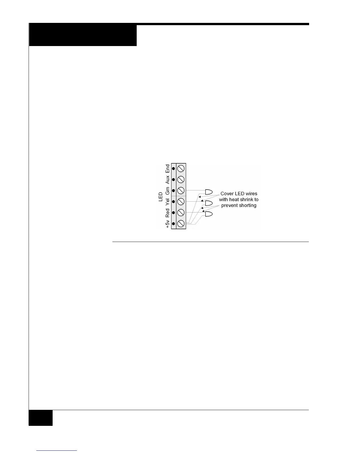
3. To test the reader LEDs, connect three LEDs to the Reader LED port as
shown in Figure 19. Connect the anode (long lead) of each LED to Pin 1
(+5v). Cover the LED wires with heat shrink to prevent short circuits.
NOTE If you are using an older LED that does not have a built-in current-limiting
resistor, add a 1K-ohm resistor in series.
FIGURE 19. Connecting LEDs for Self-Test Mode
4. Power up the RM-4E. When you power up the RM-4E:
Relays 1 and 2 toggle every second.
Reader LED lines Red, Green, and Yellow flash on and off.
The LCD displays the information shown in Figure 20.