RM-4E Components
12
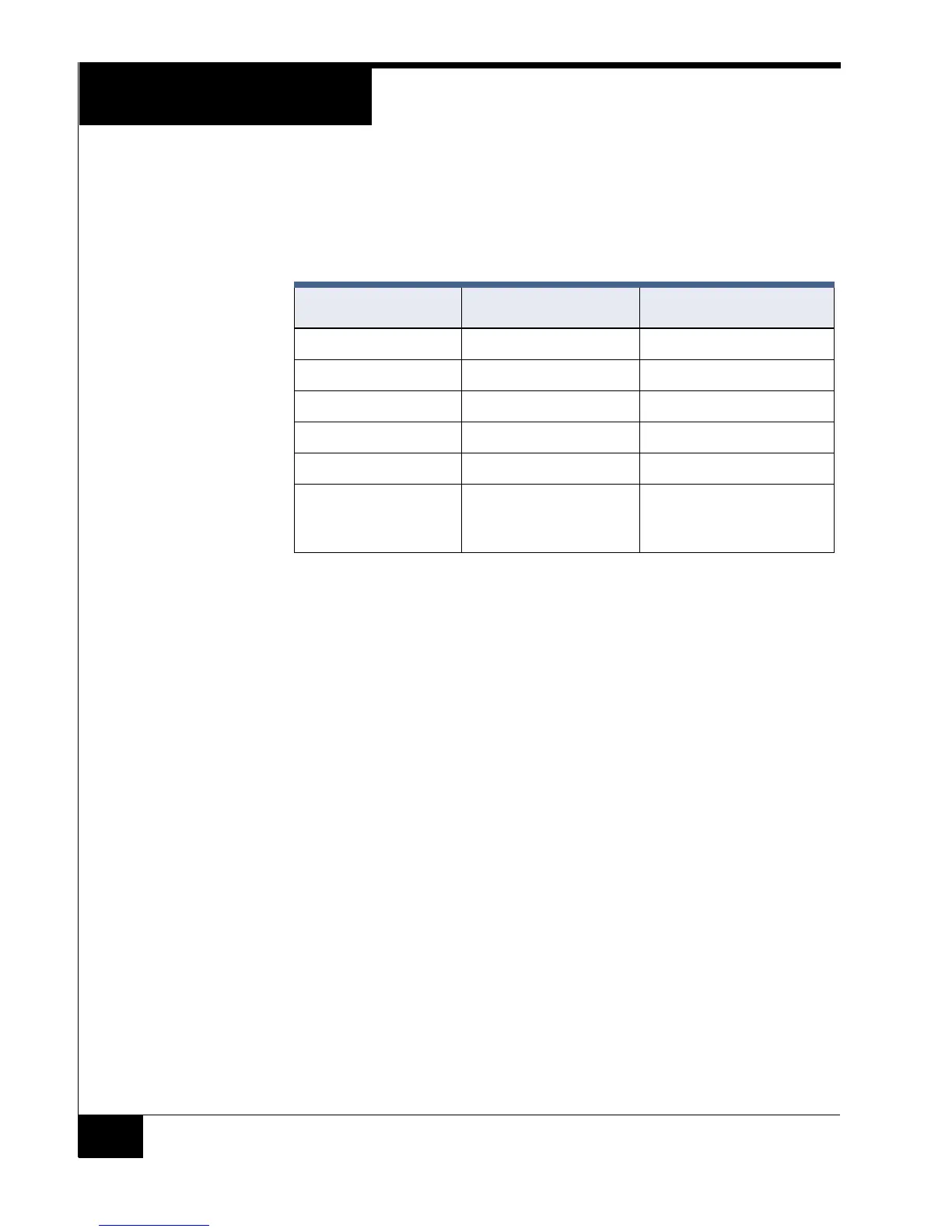
Magnetic (ABA) Signaling
For Magnetic (ABA) signaling, use the following pinout; set SW5-1 to
OFF.
NOTE UL has not evaluated magnetic (ABA) signaling read heads.
Relay 1, Relay 2,
MagLock, and Bypass
The RM-4E provides lock components that facilitate connecting magnetic
and electric strike locks.
Relay 1 is a standard Form C, dry contact relay, identical to the relays
found on the iSTAR ACM.
Relay 2, along with the MagLock and Bypass connectors have
internal etch connections for wiring magnetic and electric strike locks
Tie Point (TP1/TP2) connector pins are not connected to the circuitry.
They are used as connection points to avoid field splices when
connecting locks to Relay1. TP1-1 is tied to TP1-2, and TP2-1 is tied to
TP2-2.
Lock Connectors The Lock Connector pinouts are shown below.
TABLE 6. Magnetic (ABA) Signaling Pinout
Pin Signal Function
1 CRD N/A
2 STRB Strobe signal
3DATData signal
4 +5 VDC +5 VDC if required
5 GND Ground
6 +12 VDC +12 VDC if required (not
used by Software House
magnetic read heads)