RM-4E Components
8
RM-4E
COMPONENTS
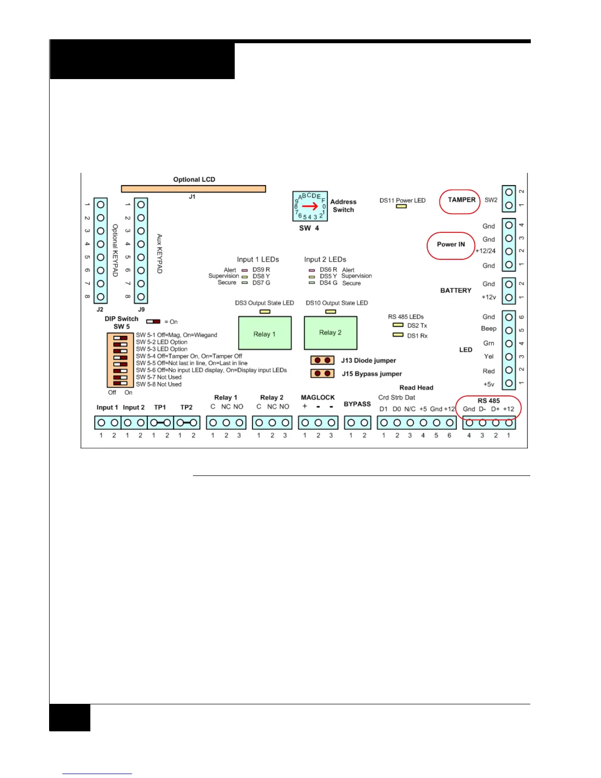
Figure 5 shows the location of connection points, switches, and LEDs on
the RM-4E board.
RM-4E Board Layout
FIGURE 5. RM-4E Board Layout
This section lists the RM-4E components — starting from the upper right
corner of Figure 5 and moving in a clockwise direction.
Tamper
The RM-DCM-2 tamper input twisted pair wires, shown in Figure 2, are
connected to the TAMPER (SW2) input pins.