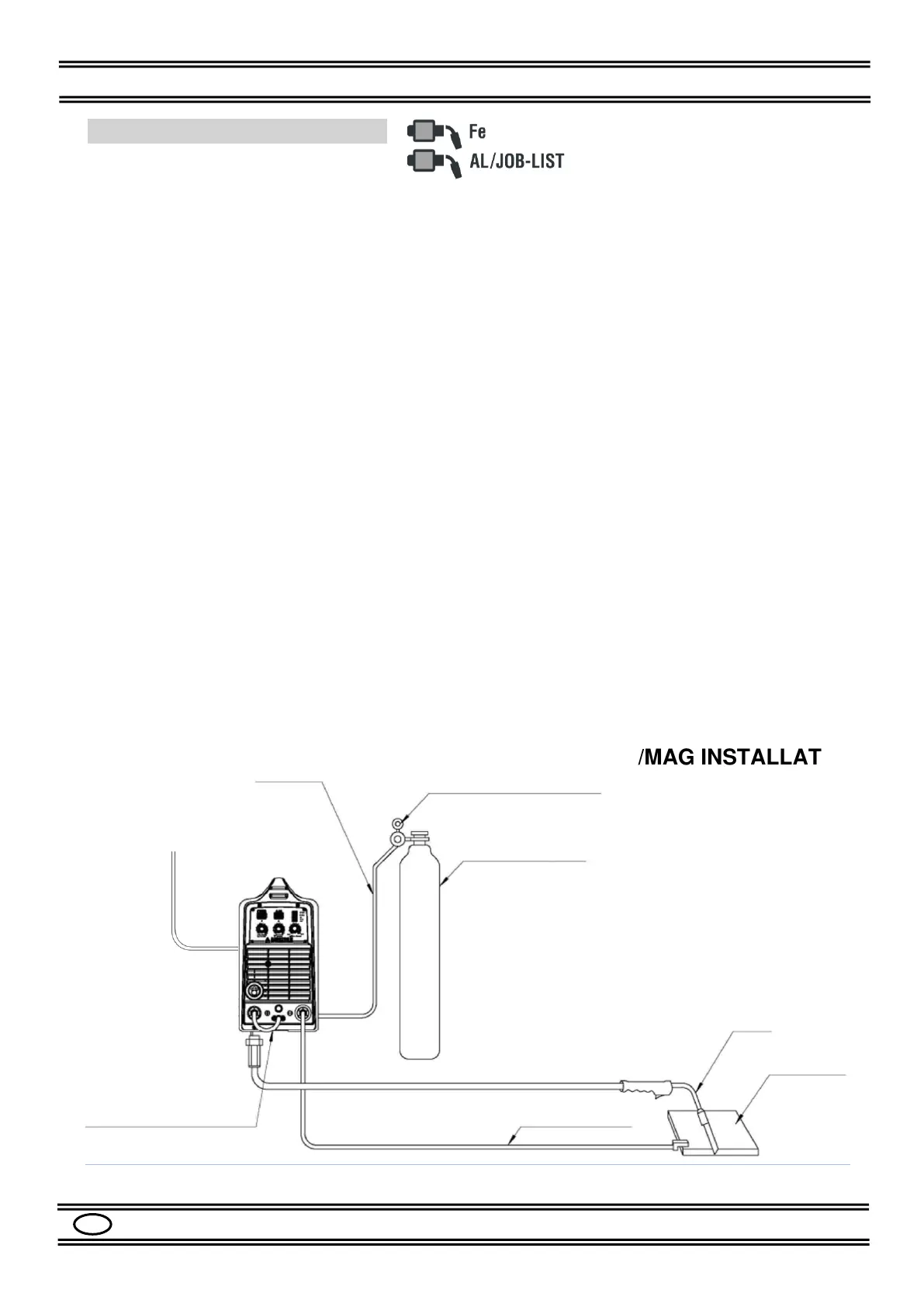
7.4 MIG/MAG INSTALLATION
Please refer to the Figures 1, 2, 3, 4.
- Make sure that the switch (9) is in the "0" position.
- Check that the selector (12) in the spool holder compartment is in the "MIG GUN"
position.
- Connect the MIG TORCH to the socket (6) of the machine.
- Connect the GROUND CABLE to the socket (3) (-) of the machine.
- Secure the other end of the ground cable to the workpiece, making sure there is good
electrical contact
- Connect the DINSE PLUG (4) to the socket (5) (+).
- Check that the drive ROLL (14) corresponds to the diameter of the wire to be used.
- Load the SPOOL of WIRE to be used in the support (15).
- Insert the wire into the wire guide tube, on the rollers and inside the torch for about 10
cm.
- Install the GAS regulator on the gas cylinder.
- Connect the GAS hose to the cylinder pressure adapter.
- Connect the other end of the GAS hose to the fitting (10).
- Open the gas cylinder regulator.
- Adjust the gas flow to the appropriate value (10-14 Lt / min).
- Turn on the machine with the switch (9).
- Press the MODE button (18) to select the AlMg1.0 or JOB-LIST mode
- Select the 2-times, 4-times or 4-times Special cycle with the CYCLE button (17).
- Set the welding values with the knobs (19), (20), (21), see Par. 8.3.
- Adjust the other welding parameters as described in Par. 8.5 and refer to Table 4.
- The machine is now ready to weld.