6. Use a pre-crimped cable to connect via gland #1 to the RJ45 plug on the inverter's
communication board or, if using a spool of cable, connect as follows:
a. Insert the cable through the gland.
b. Remove the cable’s external insulation using a crimping tool or cable cutter and
expose eight wires.
c. Insert the eight wires into an RJ45 connector, as described in
Figure 20
.
d. Use a crimping tool to crimp the connector.
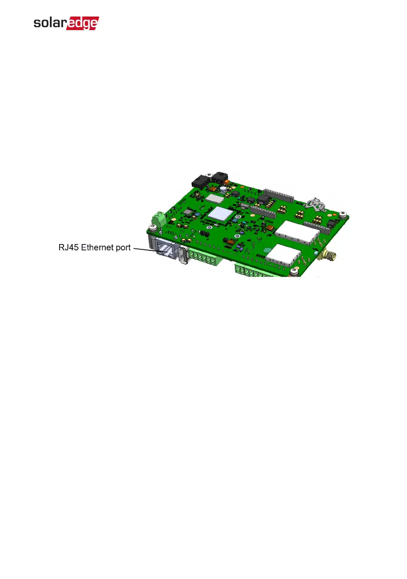
e. Connect the Ethernet connector to the RJ45 port on the communication board.
Figure 21: The RJ45 Ethernet connection
7. For the switch/router side, use a pre-crimped cable or use a crimper to prepare an
RJ45 communication connector: Insert the eight wires into the RJ45 connector in the
same order as above (
Figure 20
).
8. Connect the cable RJ45 connector to the RJ45 port of the Ethernet switch or router.
You can connect more than one inverter to the same switch/router or to different
switches/routers, as needed. Each inverter sends its monitored data independently
to the SolarEdge monitoring platform.
9.
The inverter is configured by default to LAN. If reconfiguration is required:
a. Make sure the ON/OFF/P switch is OFF.
b. Turn ON the AC to the inverter by turning ON the circuit breaker on the main
distribution panel.
c.
Configure the connection as described in
Communication
on page 34.
Chapter 6: Setting Up Communication to the Monitoring Platform 53
Single Phase Inverter with HD-Wave Technology Installation MAN-01-00540-1.0