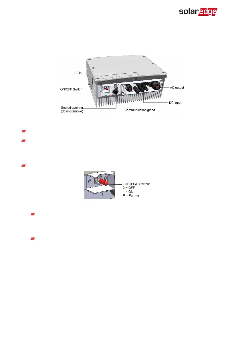
Inverter Interfaces
The following figure shows the inverter connectors and components, located at the
bottom of the inverter.
Figure 5: Inverter Interfaces
DC input: MC4 connector, for connection of the PV installation.
Communication gland: For connection of inverter communication options. Refer to
Setting Up Communication to the Monitoring Platform
on page 47 for more
information.
ON/OFF/P switch:
Figure 6: ON/OFF/P switch
ON (1) - Turning this switch ON (after optimizer pairing) starts the operation of
the power optimizers, enables power production and allows the inverter to
begin exporting power to the utility grid.
OFF (0) - Turning this switch OFF reduces the power optimizer voltage to a low
safety voltage and inhibits exportation of power. When this switch is OFF, the
control circuitry remains powered up.
Single Phase Inverter with HD-Wave Technology Installation MAN-01-00540-1.0
20 Inverter Interfaces