WARNING!
If using a dual-input power optimizer and some inputs are not used, seal the
unused input connectors with the supplied pair of seals.
AVERTISSEMENT!
Si un optimiseur à double entrées est utilisé et que certaines entrées ne sont
pas connectées, fermez ces entrées avec la paire de couvercles fournie.
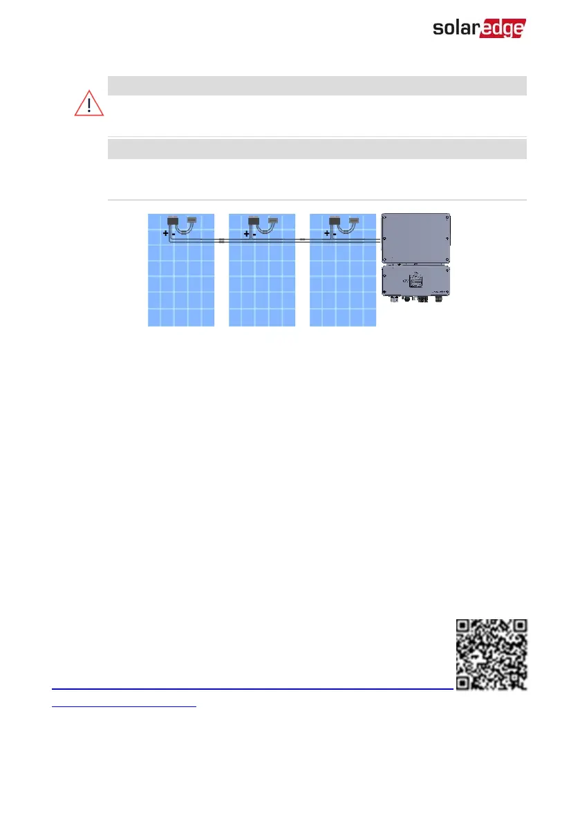
Figure 9: Power optimizers connected in series
3.
If you intend to monitor the installation, using the monitoring platform, record the
physical location of each power optimizer, as described in
Creating Logical and
Physical Layout using Installation Information
on page 44.
Step 4: Verifying Proper Power Optimizer Connection
When a module is connected to a power optimizer, the power optimizer outputs a safe
voltage of 1V (±0.1V). Therefore, the total string voltage should equal 1V times the
number of power optimizers connected in series in the string. For example, if 10 power
optimizers are connected in a string, then 10V should be produced.
Make sure the PV modules are exposed to sunlight during this process. The power
optimizer will only turn ON if the PVmodule provides at least 2W.
In SolarEdge systems, due to the introduction of power optimizers between the PV
modules and the inverter, the short circuit current I
SC
and the open circuit voltage V
OC
hold different meanings from those in traditional systems.
For more information about the SolarEdge system’s string voltage and
current, refer to the
V
OC
and I
SC
in SolarEdge Systems Technical Note
,
available on the SolarEdge website at:
https://www.solaredge.com/sites/default/files/isc_and_voc_in_solaredge_
sytems_technical_note.pdf
Single Phase Inverter with HD-Wave Technology Installation MAN-01-00541-1.3
24 Step 4: Verifying Proper Power Optimizer Connection