Inverter Interfaces
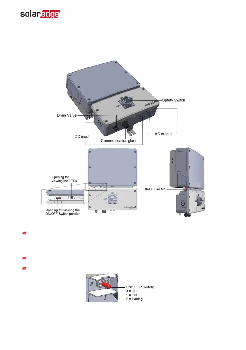
The following figure shows the inverter connectors and components, located at the
bottom of the inverter.
Figure 10: Inverter Interfaces
Communication gland: For connection of inverter communication options. Refer to
Setting Up Communication to the Monitoring Platform
on page 47 for more
information.
Drain valve: Drains any moisture that may be accumulated in the unit.
ON/OFF/P switch:
Figure 11: ON/OFF/P switch
Chapter 3: Installing the Inverter 27
Single Phase Inverter with HD-Wave Technology Installation MAN-01-00541-1.3