NOTE
You can use the activation code that appears on the certification
inverter label to activate the inverter in case of a script error or a missing
activation card.
4. Verify that the inverter is configured to the proper country: Press the LCD light
button until reaching the ID status screen:
I D : # # # # # # # # # #
D S P 1 / 2 : 1 . 0 2 1 0 / 1 . 0 0 3 4
C P U : 0 0 0 3 . 1 9 x x
C o u n t r y : E S P
5.
If required, perform the following additional steps before closing the inverter cover:
Country settings or inverter configuration using the internal LCD user buttons –
refer to
Country and Grid
on page 51.
Communication options connection – refer to
Setting Up Communication to the
Monitoring Platform
on page 65.
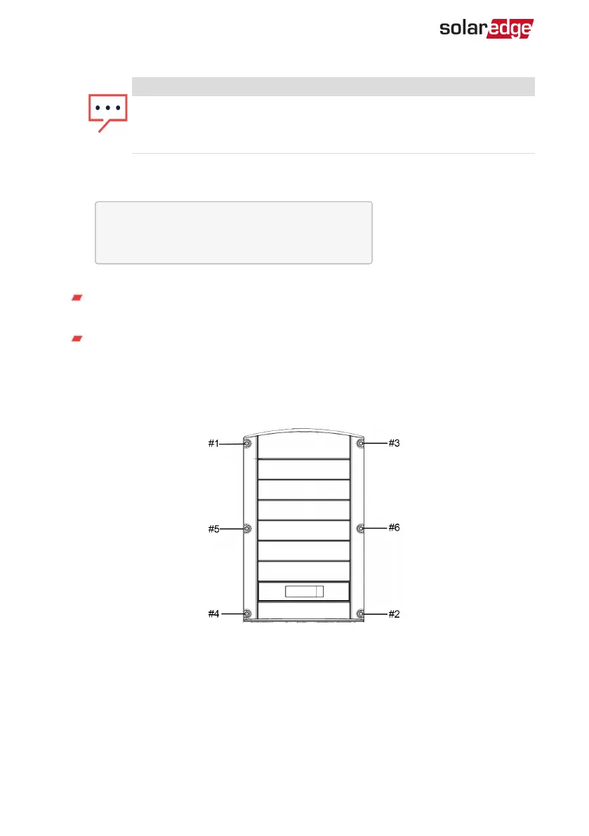
6.
Close the inverter cover by tightening the screws with a torque of 10.3 N*M/ 7.5
lb*ft. For proper sealing, first tighten the corner screws and then the two central
screws. The following figure illustrates recommended order:
Figure 17: Tightening order of the screws
7.
Turn ONthe DC Safety Unit (if applicable) . If an additional external DC switch is
installed between the power optimizers and the inverter(s) then turn it ON.
A status screen similar to the following appears on the LCD panel:
Three Phase System MAN-01-00507-4.2
36 Step 1: Activating the System