1. Remove the inverter cover as described in
Removing the Inverter Cover
on page 69.
2. Remove the seal from one of the openings in communication gland #2 and insert
the wire through the opening.
3.
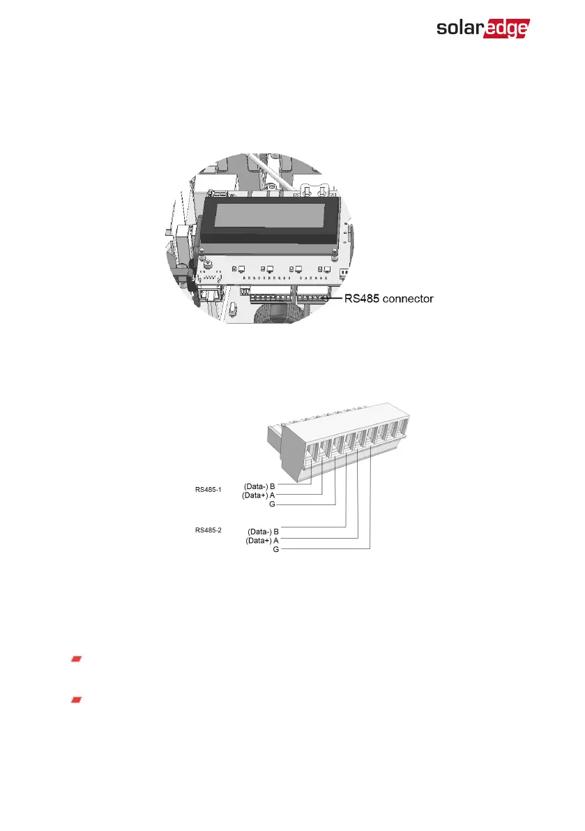
Pull out the 6-pin RS485 terminal block connector, as shown below.
Figure 25: RS485 terminal block on the communication board
4.
Loosen the screws of pins A(+), B(-), and G on the left of the RS485 terminal block
(RS485-1 or RS485-2).
Figure 26: RS485 terminal block
5.
Insert the wire ends into the G, A and B pins shown above. Use Four- or six-wire
twisted pair cable for this connection.
You can use any color wire for each of the A, B and G connections, as long as:
The same color wire is used for all A pins the same color for all B pins and the
same color for all G pins
The wire for G is not from the same twisted pair as A or B.
6.
For creating an RS485 bus - connect all B, A and G pins in all inverters.
Three Phase System MAN-01-00507-4.2
74 Creating an RS485 Bus Connection