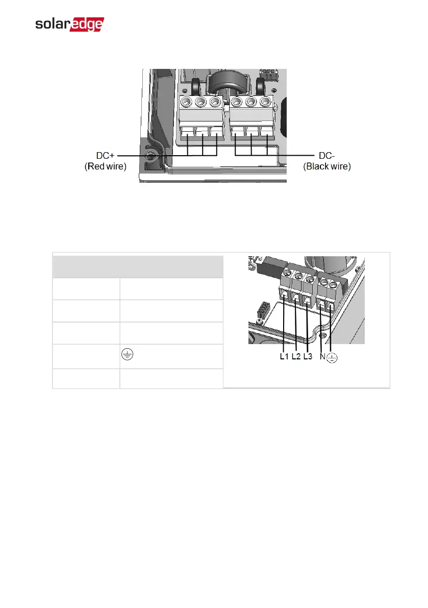
Figure 40: DC terminals
3.
Connect the AC wires according to the labels on the ACterminal blocks, as follows:
Wire type Connect to terminal
Figure 41: AC terminals
Line 1 L1
Line 2 L2
Line 3 L3
PE (grounding)
Neutral N
4. Tighten the screws of each terminal with a torque of 1.2-1.5 N*m / 0.88-1.1 lb.*ft.
5. Verify that there are no unconnected wires at the output of the DC Safety Unit and
that any unused terminal screws are tightened.
6. Connect the DC and AC wires to the DC Safety Unit. Refer to
Connecting the AC and
the Strings to the Inverter
on page 30.
7. Ensure proper cable entry sealing; inspect the entire cable run and use standard
sealants to avoid water penetration.
Appendix F: Replacing and Adding System Components 95
Three Phase System MAN-01-00507-4.2