CAUTION!
Drilling vibrations may damage the power optimiser and will void the
warranty. Use a torque wrench or an electric drill with adjustable clutch that
meets the mounting torque requirements.
Do not
use impact drivers for
mounting the power optimiser.
Do not
drill through the power optimiser or through the mounting holes.
3.
Attach each power optimiser to the rack using M6 (1/4'') stainless steel bolts, nuts
and washers or other appropriate mounting hardware. Apply torque of 9-10 N*m /
6.5-7 lb*ft.
4. Verify that each power optimiser is securely attached to the panel support structure.
5. Record power optimiser serial numbers and locations, as described in
Reporting and
Monitoring Installation Data
on page 49.
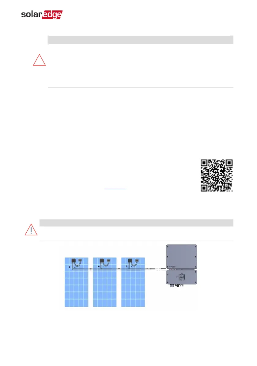
Step 2: Connecting Power Optimisers in Strings
You can construct parallel strings of unequal length, that is, the number
of power optimisers in each string does not have to be the same. The
minimum and maximum string lengths are specified in the power
optimiser datasheets. Refer to the Designer for string length verification.
1. Connect the Minus (-) output connector of the string’s first power optimiser to the
Plus (+) output connector of the string’s second power optimiser
2. Connect the rest of the power optimisers in the string in the same manner.
WARNING!
If using a dual-input power optimiser and some inputs are not used, seal the
unused input connectors with the supplied pair of seals.
Figure 4: Power optimisers connected in series
Chapter 2: Installing the Power Optimisers 20
EV Charging Single Phase Inverter MAN-01-00629-1.2