5.
Remove the plastic cover from the battery terminals.
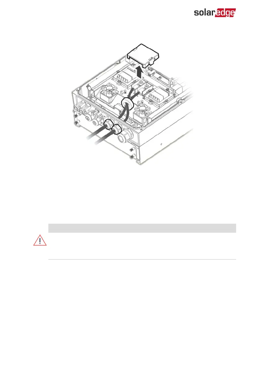
Figure 15: Connection of Battery DCCables to the Inverter
6. Pass the non-crimped ends of the DCcables through a 48 mm ferrite bead supplied
with the inverter.
7.
Pass the non-crimped ends of the DCcables from the inside of the inverter
outwards, through the battery DCinput glands. The correct polarity is marked on
the inverter.
WARNING!
Make sure to connect the power cables at correct polarity. Connecting the
power cables at reverse polarity may result in damage to the inverter or
battery.
8.
Connect the DC cables to the battery terminals of the inverter. Tighten the terminals
with the supplied M8 screws with a torque of 5N*m/3.7lb*ft.
9. Reinstall the plastic cover on the inverter's battery terminals.
10. Tighten the battery DCinput glands.
Connecting the CANBus Cable
Communication between the inverter and battery is established using the Controlled
Area Network (CAN) bus. Use a shielded Ethernet cable (CAT5/5E STP/6).
StorEdge Three Phase Inverter MAN-01-00648-1.3
37 Connecting the Battery

 Loading...


