DRM4/8
+3.3V
DRM0
GND GND
1 2
3
4
5
6 7 8
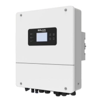
The BMS pin is defined as follows:
The DRM pin is defined as follows:
1 2
3
4
5
6 7 8
DRM1/5 DRM2/6 DRM3/7
1 2 3 4 5 6 7 8
1
8
Ø BMS communication cable
Ø DRM communication cable
1
8
BMS_CANH
GND
BAT_TEMP
GND
BMS_CANL
2
3
4
5
6 7 8
1
X
BMS_485A BMS_485B
Notice!
Electrical Connection
Electrical Connection
54
55
Notice!
The BMS port on the inverter is the communication port for connecting
the battery. The communication port on the lithium battery must be
consistent with the definition of pins 4, 5, 7, and 8 above.
At present, there are only PIN6 (DRM0) and PIN1 (DRM1 /5), and
other PIN functions are under development.
Ø Application occasion
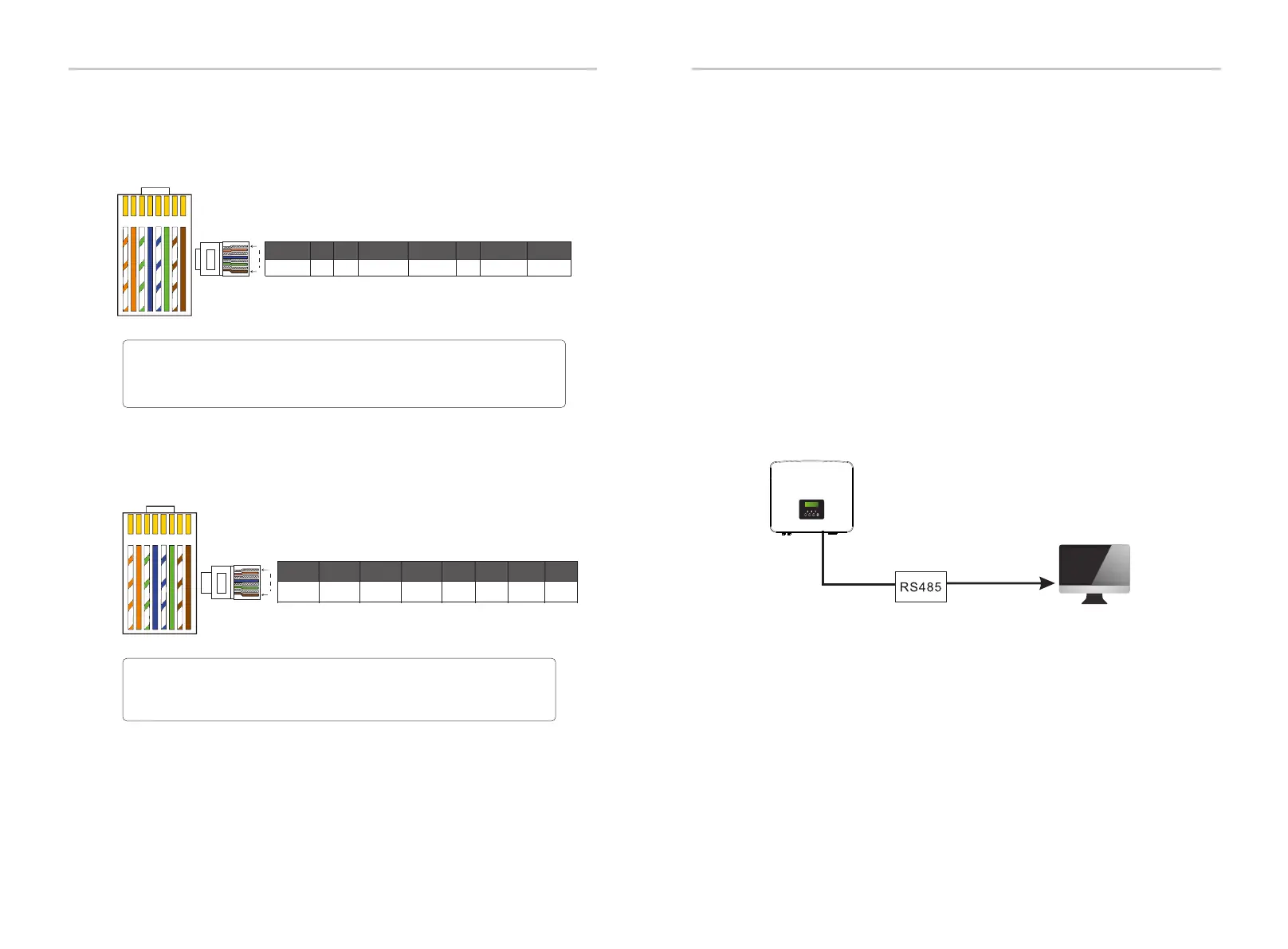
5.5.3 COM Communication
Data Read
External communication equipment controls the inverter
●
COM communication interface is mainly provided for customization
the second step of development use. The inverter supports the control
of external equipment or external equipment control through
communication. For example, the inverter adjusts the working mode
of the heat pump and so on.
COM is a standard communication interface, through which the
monitoring data of the inverter can be directly obtained. Also, external
communication devices can be connected to carry out the secondary
development of the inverter. For specific technical docking,
please contact SolaX.

 Loading...