Electrical Connection
Electrical Connection
66
67
Ø Ground connection steps
C
One-core cable (4 mm)
OT terminal
4 mm
Leaking cable
Hexagon socket screws
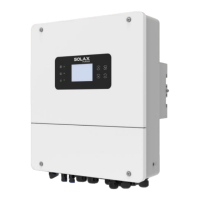
Diagonal pliers
L2=L1+3 mm
L1
Crimping Tool
5.6 Grounding Connection (Mandatory)
Step 1. Prepare a one-core cable (4 mm), and then find the ground
terminal in the accessories.
The user must make two ground connections: one shell grounding, and
one equipotential grounding.This prevents electric shock.
Step 2. Strip the grounding cable insulation(length”L2"), insert the
stripped cable into the ring terminal, and then clamp it.
Step 3. Insert the stripped cable into OT terminal and tighten the
terminal with a terminal crimping tool.
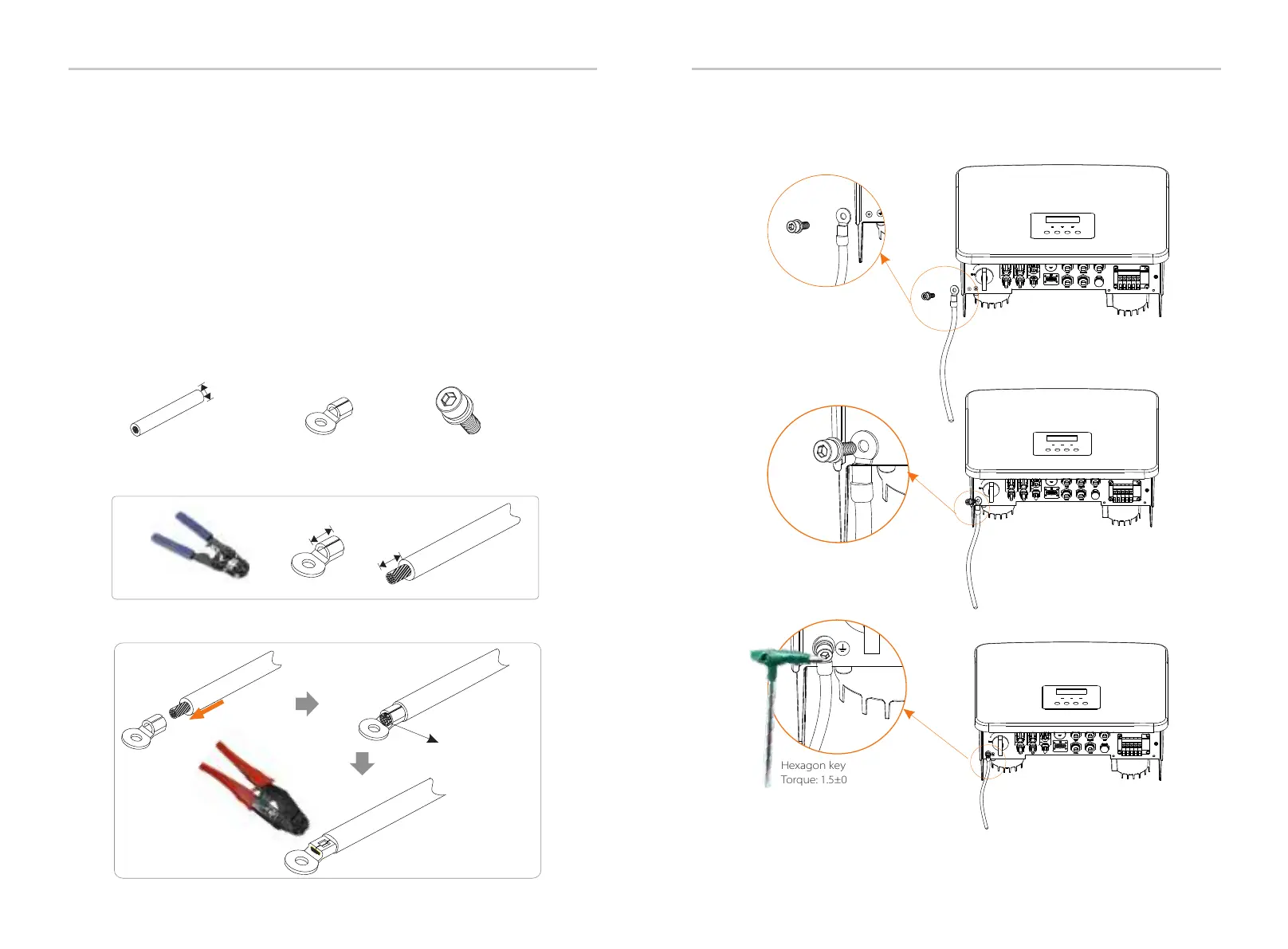
Hexagon keys
Torque: 1.5±0.2N·m
Upgrade/Dongle
Upgrade/Dongle
Upgrade/Dongle
Step 4. Find the ground connection port on the inverter, and screw the
ground wire on the inverter with an M5 Hexagon keys.
Notice: In the event of an Earth Fault, the inverter will turn on a red
light and report ISO Fault. This inverter complies with IEC 62109-2
clause 13.9 for earth fault alarm monitoring.
The product must be installed in a high traffic area where the red
light would be noticed.
The ground wire port of X1-Hybrid G4 M series inverter has been
connected, and the D series needs to be wired according to the
following steps.

 Loading...