7
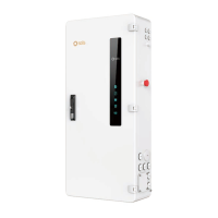
Load Connection
Smart Backup Load is controllable through Solis Hub while the
Grid Load is non-backup load on the AC grid side. Customer can
connect the loads accordingly based on the needs.
Step 1. Lead the load AC wires from the conduits on the right side
or bottom of the Solis Hub.
Step 2. Connect the corresponding loads to the smart load terminals
(Load 1 – Load 4) or the non-Backup load terminal (Grid Load).
Use a slotted screwdriver and insert to the square port on the left
side of the terminal and then insert the AC wire to the round port on
the right side of the terminal. Release the screwdriver to fasten the
wires.
Step 3. Connect the load neutral wire to the neutral bar terminal .
N/A Slotted Screwdriver
Terminal
Torque
Screwdriver Type
Wire Size
Load 1 - 4
6 AWG
N/A Slotted Screwdriver
Grid Load 6 AWG
250 Lb.In
Phillips screwdriver
Neutral
6 AWG
All load port are designed to handle rated 60A.
NOTE:
8
Generator Connection
Step 1. Bring the AC cables for generator into the Solis Hub from the
right side.
Step 2. Strip ½ inch of insulation from the ends of each cable.
Step 3. Insert a technician screwdriver into the small hole on the
wire terminal.
Step 4. Pull the screwdriver to the right side to fasten the terminal
and then release the screwdriver
Step 5. Give the wire a gentle tug test to ensure it is tight.
Step 6. If the wire feels loose, repeat steps 3-5.
N/A Screwdriver
Terminal
Torque
Screwdriver Type
Wire Size
GEN L1 L2 6 AWG
9
Communication
CAN: RJ45 Connector - Connect to the master inverter ’s
Parallel _A Port;
ETHERNET: RJ45 Connector - Connect to the master inverter’s
SPH-IN Port;
EPO IN/ EPO OUT: Connect to the master inverter's EPO IN/
EPO OUT to realize emergency power off function;
Dry_Con_B / Dry_Con_A: If a remote remote motor is required,
the generator remote start signal needs to be connected to the
Dry_contact1_A and Dry_contact1_B;
RS485A / RS485 B: Reserved
10
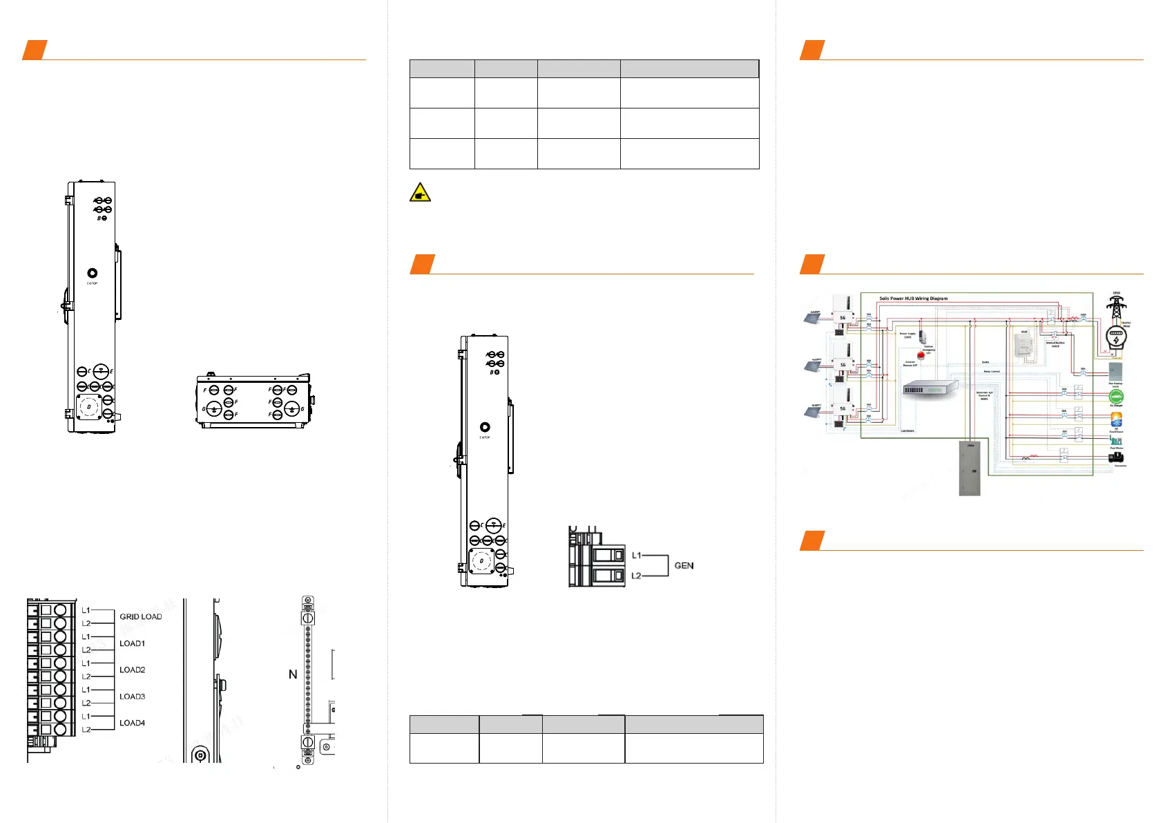
Overall System Diagram
Ginlong Technologies Co., Ltd.
No. 57 Jintong Road, Binhai Industrial Park,
Xiangshan, Ningbo, Zhejiang, 315712, P.R.China.
Tel: +86 (0)574 6578 1806
Fax: +86 (0)574 6578 1606
Email: info@ginlong.com
Web: www.solisinverters.com
Contact us
11
 Loading...