4. Installation 4. Installation
Pre-made Cable in Meter Package
RJ45 Connector
Pre-made Cable
in Meter Package
RJ45 Connector
INV L
INV N
INV PE
Grid L
Grid N
Grid PE
CT Arrow
Grid
White Black
+ -
L N PE
Load
5 6 7 8 9 10 21 22 23
1 2 3 4 13 12
INV L
INV N
INV PE
Grid L
Grid N
Grid PE
5 6 7 8 9 10 21 22 23
1 2 3 4 13 12
2-Pin Connector
L N PE
Load
CT Arrow
Grid
White Black
+ -
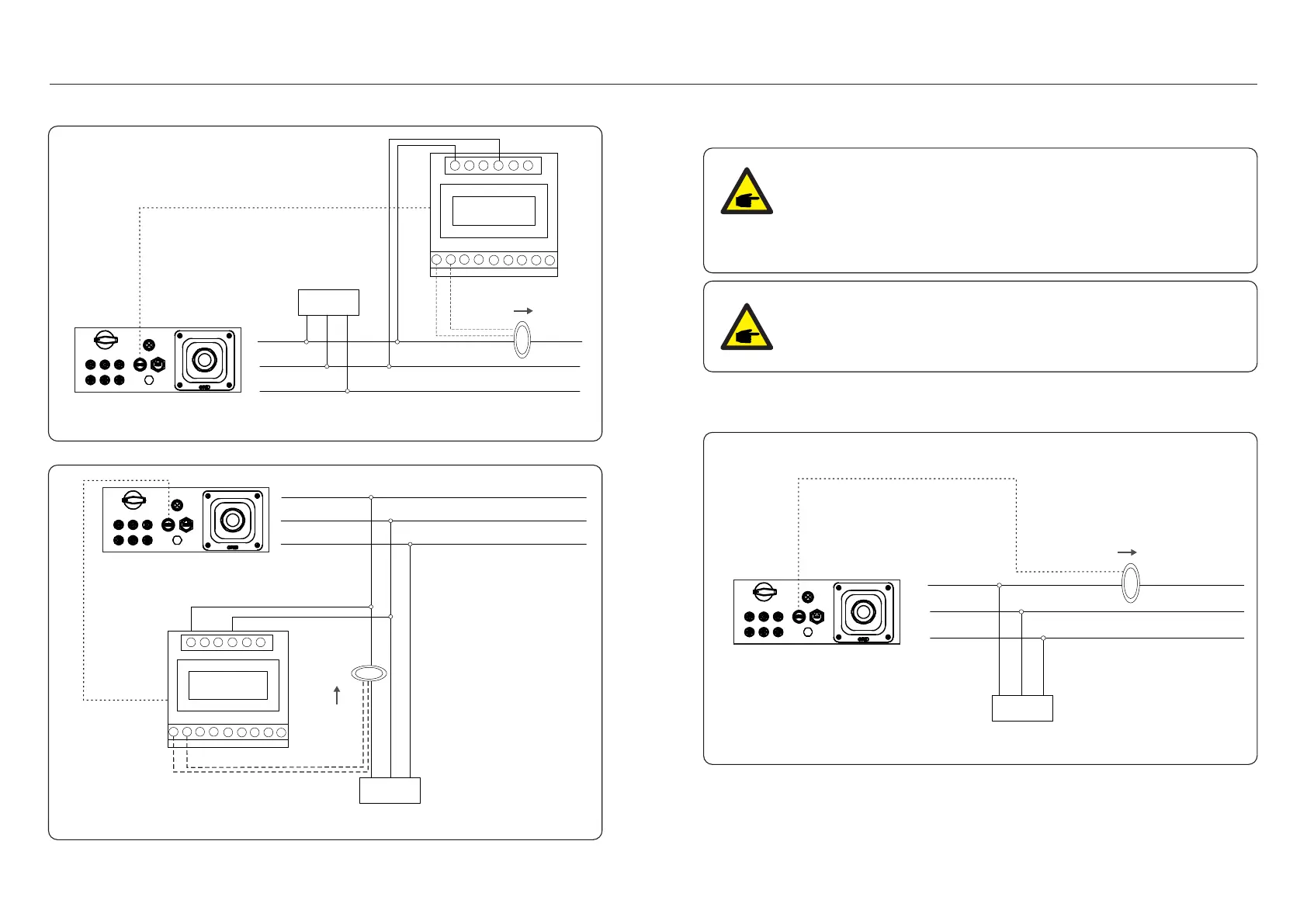
Figure 4.25 External CT Type Meter - “Meter in Grid”
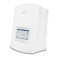
Figure 4.26 External CT Type Meter - “Meter in Load”
4.3.8 CT connections(optional)
The inverter can work with a smart sensor to achieve Export Power Management function.
Below is the connection diagram of the smart sensor.
Detailed settings please refer to Section 6.5.12.
Pre-made Cable in CT Package
2-Pin Connector
Grid L
Grid N
Grid PE
INV L
INV N
INV PE
L N PE
Load
CT Arrow
Grid
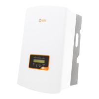
Figure 4.27 Smart Sensor
Inverters are classified as "Meter Model" and "CT Model" due to hardware
difference.
Meter Model can only connect a smart meter.
CT Model can only connect a smart sensor.
Please consult Solis Sales Rep before placing the order.
NOTE:
To achieve Export Power Management function, the smart sensor
must be installed on the grid side.
NOTE:
.23..22.
2-Pin Connector