4. Installation4. Installation
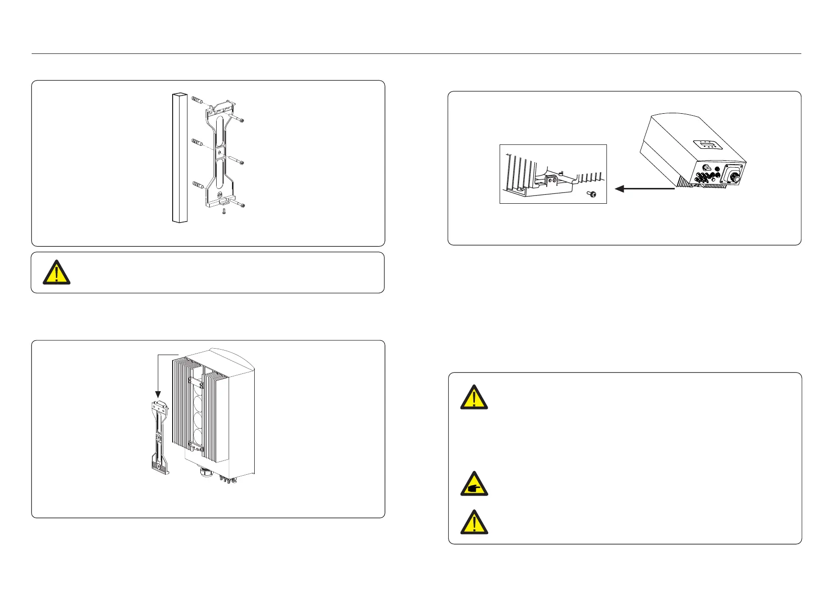
Figure 4.5 Inverter pillar mounting
WARNING:
The inverter must be mounted vertically.
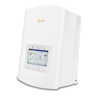
4. Lift up the inverter (be careful to avoid body strain), and align the back bracket on the
inverter with the convex section of the mounting bracket. Hang the inverter on the
mounting bracket and make sure the inverter is secure (see Figure 4.6).
Figure 4.6 Wall Mount Bracket
5. Use screws to fix the bottom of the inverter to the mount bracket.
Figure 4.7 Fix the inverter
The are two holes at the bottom of bracket, one to fix the inverter, another for the lock.
The diameter of the lock should be less than 0.27in (7mm).
4.3 Electrical Connections
4.3.1 Connect PV side of inverter
The electrical connection of the inverter must follow the steps listed below:
1. Switch the Grid Supply Main Switch (AC) OFF.
2. Switch the DC Isolator OFF.
3. Assemble PV input connector to the Inverter.
Before connecting inverter, please make sure the PV array open circuit
voltage is within the limit of the inverter.
Before connection, please make sure the polarity of the output voltage of
PV array matches the“DC+”and“DC-”symbols.
Please don’t connect PV array positive or negative pole to the ground, it could
cause serious damages to the inverter.
Maximum 600Vdc for
S5-GR1P7K, S5-GR1P8K,
S5-GR1P9K, S5-GR1P10K
.12. .13.