User Manual
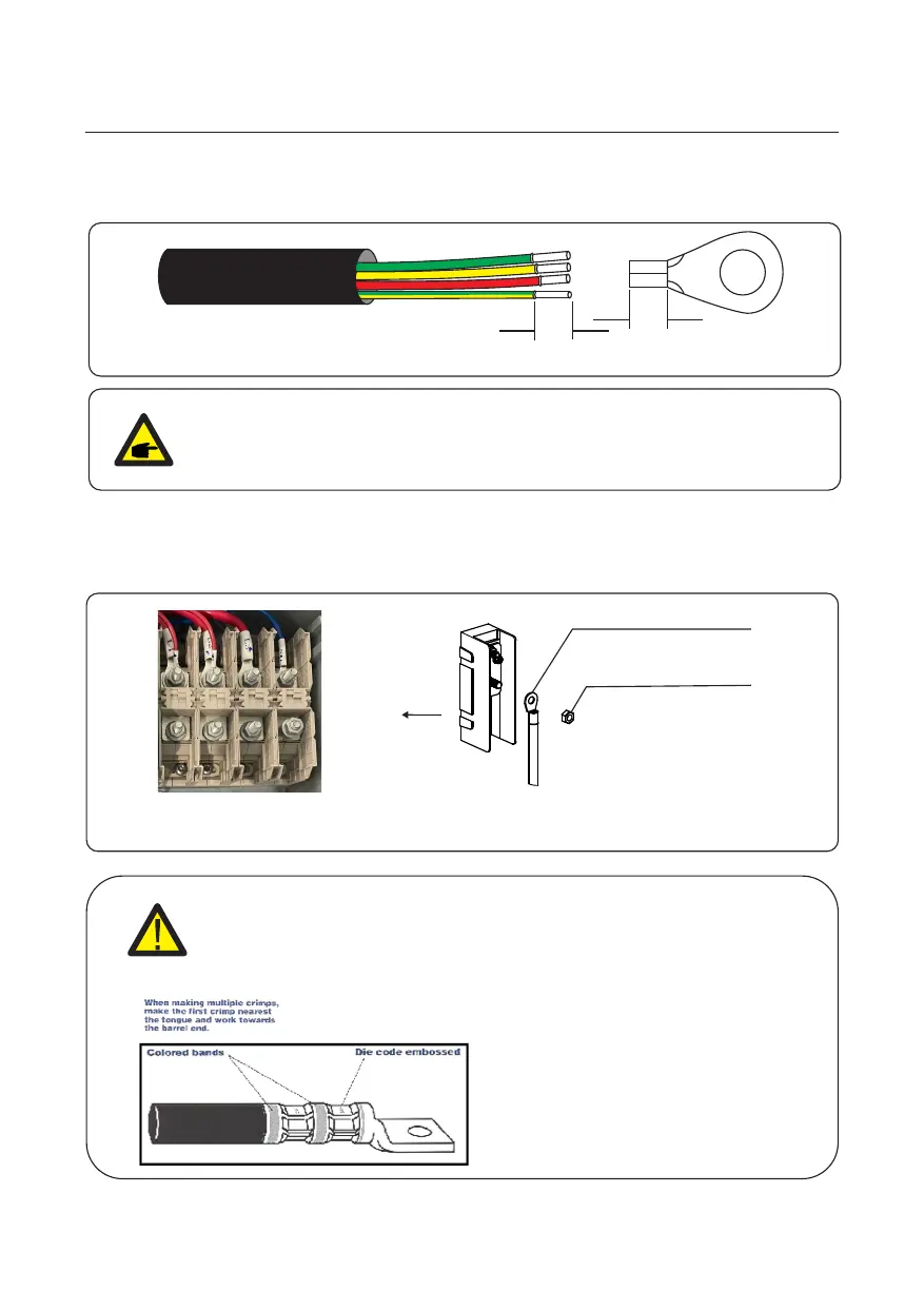
Figure 3.28 AC Terminal Connection
Copper terminal of cable
nut
3. Installation
27
L1 L2 L3 N
Figure 3.27 Strip AC cable
PE
L
S2
S1
NOTE
S2 (insulation stripping length) is 2mm-3mm longer than S1.
(OT cable terminal crimping area)
2. Strip the insulation of the wire past the cable crimping area of the OT terminal, then use a
hydraulic crimp tool to crimp the terminal. The crimped portion of the terminal must be
insulated with heat shrinkable tube or insulating tape.
1. Strip the end of AC cable insulating jacket about 11.8 inch then strip the end of each wire.
The steps to assemble the AC grid terminals are listed as follows:
WARNING
Installer must use manufacturer approved crimping tools and crimping guide
for proper connector installation. Improper crimping of the connector
will void inverter warranty.
When crimped, the die code number or
other marking will be embossed on the
connector for easy inspection to
determine if correct die and connector
combination were used
 Loading...