EasyManuals Logo

SOLIS S6-EH3P5K2-H User Manual

SOLIS S6-EH3P5K2-H
91 pages
To Next Page IconTo Next Page
To Previous Page IconTo Previous Page
Page #34 background imageLoading...
Page #34 background image
User Manual
4. Comm. & Monitoring
29
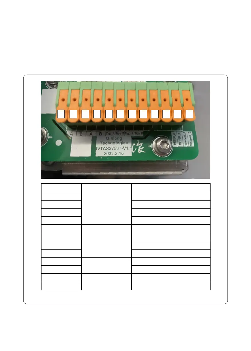
1 2 3 4 5 6 7 8 9 10 11 12
The inverter package will include a 12-Pin connector.
The Pin definition is shown below. Facing the connector, Pin 1 is on the left of the first row.
The rest polarity is showing in below diagram.
PIN Definition Description
1 RS485 A IN
2 RS485 B IN
3 RS485 A OUT
4 RS485 B OUT
5 RS485 A IN
6 RS485 B IN
7 RS485 A OUT
8 RS485 B OUT
9 RS485 A
10 RS485 B
11 / Reserved A
12 / Reserved
Transmitter
TIGO)
RS485
Meter
Figure 4.1 12-pin connector
4.1 RS485 Communication

Table of Contents

Other manuals for SOLIS S6-EH3P5K2-H

Questions and Answers:

Question and Answer IconNeed help?

Do you have a question about the SOLIS S6-EH3P5K2-H and is the answer not in the manual?

SOLIS S6-EH3P5K2-H Specifications

General IconGeneral
BrandSOLIS
ModelS6-EH3P5K2-H
CategoryInverter
LanguageEnglish

Related product manuals