+-AB ODTVENTDEH
Sensor DampersRemote
FLOAT
Switch
DH DH
Gh Rf Cf Gs YW
HVAC EQUIP.
G
R
C
W
Y
R
C
G
W
Y
HVAC
EQUIPMENT
THERMOSTAT
EXISTING WIRE
NEW WIRE
OPTIONAL
WIRES
90-1859
(40 VA min)
24 VAC
(PRIMARY ZONE)
NORMALLY CLOSED
+ -AB ODT VENT
Sensor DampersRemote
DHDH
Gh Rf Cf Gs YW
HVAC EQUIP.
(SECONDARY ZONE)
NORMALLY OPEN
DEH
FLOAT
Switch
90-1896
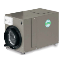
NOTE: Use 18-22 AWG wire for wiring to HVAC system
and zone dampers.
Pull off the wiring access cover near the dehumidier control
to access the wiring terminals. Snap the wiring access cover
back into place after completing all wiring.
WIRING TO THE HVAC SYSTEM
When the dehumidier is ducted to the HVAC system, it
is recommended that it also be wired to the HVAC system
as shown in Figure 22. If ducted to the HVAC system
in return to return conguration, the dehumidier must
be wired to the HVAC system to prevent short circuiting
dehumidied air directly back to the dehumidier inlet. In
return to supply ducting conguration, running the HVAC
fan with the dehumidifier ensures the warm dry air is
mixed with room air before being discharged to the home.
NOTE: Make sure the external static pressure does not
exceed the maximums shown on page 2, and disable
dehumidication during active air conditioning (see
DEH W/AC on page 13).
Optional W & Y Wiring
Wire the W and/or Y terminal to the HVAC system when
using the ventilation feature of the dehumidifier (see
Ventilation on page 16).
Wire the dehumidier Y terminal to the HVAC system if
it is desired to disable the dehumidier compressor from
operating when the air conditioning is running. See DEH
W/AC in System Set-up on page 13 for additional set up
steps required to access this feature.
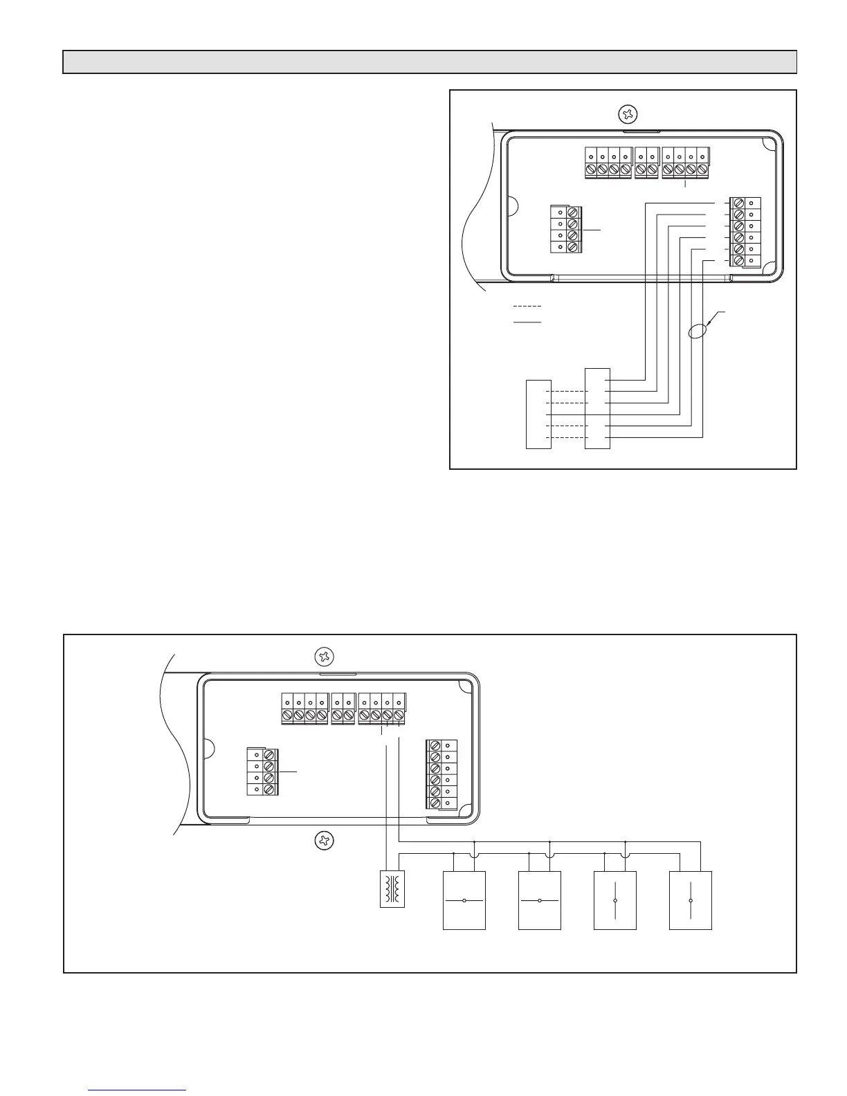
WIRING TO ZONE DAMPERS
Wiring the Dehumidier to the HVAC System and Zone Dampers
Figure 22. Wiring to HVAC System
Figure 23. Two Zone Wiring On-Board Control
11